How to Use SPI on the Particle Photon
2019-05-30 | By Maker.io Staff
The Particle Photon offers an incredible amount of processing power in an IoT prototyping platform that is both maker-friendly and professional. However, the Particle Photon has more capability than you may realize, so in this How-To, we will learn how to use the SPI peripheral on the Photon for communication with SPI hardware such as card readers, flash memory, and displays.
SPI as a Bus
SPI is an acronym for Serial Peripheral Interface and is more similar to UART than it is to I2C. SPI is used by microcontrollers to interact with external peripherals such as serial memory, real-time clocks, displays, and controllers just like I2C, however, SPI is fundamentally different. First of all, SPI uses separate data wires for data going to the microcontroller and data coming out of the microcontroller, whereas I2C has both data in and data out on the same wire (SDA). While this may result in more wires to route, it also means that data can stream in and out of a control simultaneously, and this can dramatically increase data bandwidth.
On the topic of speed, SPI is incredibly simple (with a simple shift register design) and is often available in high speeds, whereas I2C is slowed by a large number of control bytes and its slow clock rates. For example, SPI clock speeds can be as high as 60MHz, while I2C is lucky to push 1MHz clock speeds. This makes SPI useful in displays and flash memory where speed is crucial.
SPI does not use addressing in its protocol and instead uses a dedicated chip-select wire that connects the microcontroller and peripheral device directly, whereas I2C does addressing in software. This makes I2C less messy on the hardware side: an I2C device needs only two wires to a master whereas an SPI device needs at least 3 (often more with reset and command/data signals needed too).

SPI inside master and slave devices is nearly identical to shift registers

Photon Hardware SPI
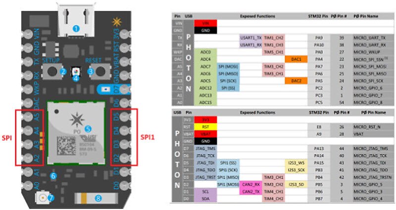
The Particle Photon has two dedicated SPI modules that are located on both the digital and analog pins. The SPI peripheral that you decide to use will depend on what pins you need in your project and the speed that you need to operate at. For example, the standard SPI module operates at a maximum speed of 30MHz, whereas the SPI Module 1 can operate as fast as 60MHz.
SPI Module (standard SPI module)
- A5 – MOSI (Master Out Serial In)
- A4 – MISO (Master In Serial Out)
- A3 – SCK(Serial Clock)
- A2 – SS (Slave Select)
SPI Module 1 – (high-speed SPI module)
- D2 – MOSI (Master Out Serial In)
- D3 – MISO (Master In Serial Out)
- D4 – SCK (Serial Clock)
- D5 – SS (Slave Select)

Using SPI
Using the SPI peripherals is very easy, and while there are many functions related to SPI, only a handful are needed for typical operation. Firstly, using SPI does not require the inclusion of any library as it is a part of the main API, and for the Particle Photon, there are two SPI objects that you can choose from: SPI and SPI1. Be sure that you reference the correct object; otherwise, you will be using the wrong module!
BEGIN()
Just like serial ports, the begin() function needs to be called before an SPI object can be used. This function can take several arguments, but these arguments are optional. The first optional argument is the SPI mode, and the second optional argument is for an alternative slave select pin if you do not wish to use the default slave select pin. The two SPI modes available are SPI_MODE_MASTER and SPI_MODE_SLAVE and they allow for the Photon to behave as either a master or slave device. In most cases, you will pass no arguments and just use .begin().
SPI.begin();	// Initiate the SPI module
SPI1.begin();	// Initiate the second SPI module
END()
End() is the opposite of begin() and disables the SPI module.
SPI.end(); // Disable the peripheral
SETBITORDER()
This function is important when you need to choose the bit order of the output. For example, some devices may stream out the most significant bit first, while others stream out the least significant bit first. The argument passed to this function is either LSBFIRST or MSBFIRST. Chances are you will not need to use this function, but do check which bit your SPI device expects first!
SPI.setBitOrder(LSBFIRST); // Send the least significant bit first.
This function is used to set the clock speed of the SPI clock line. Different SPI devices operate at different speeds, so this function needs to be used to get the clock speed correct. You can either pass a number followed by a unit or just a number in Hertz.
SPI.setClockSpeed(1, MHZ);	// Set SPI clock to 1MHz
SPI.setClockSpeed(100000);	// Set SPI clock to 100kHz
This function takes a single byte and sends this byte to the connected SPI device and also receives a byte from the connected device simultaneously. This function will return the byte received from the device.
unsigned char data = SPI.transfer(0x5A); // Send the byte 0x5A to the connected device but // also receive a single byte from the device too
Simple SPI example
unsigned char dataBuffer[100];

void setup()
{
    SPI.begin();                    // Initiate SPI
    SPI.setClockSpeed(1, MHZ);      // Set our clock speed to 1MHz
    Serial.begin(9600);             // Open a serial port connection
}

void loop()
{
    // Stream out 100 incremental numbers
    for(unsigned char i = 0; i < 100; i ++)
    {
        // Send i out and receive a byte into dataBuffer
        dataBuffer[i] = SPI.transfer(i);
    }

    // Print out the results
    for(unsigned char i = 0; i < 100; i ++)
    {
        Serial.print(String(dataBuffer[i]) + " ");
    }

    // Print a new line
    Serial.println("");
}


 中国
中国