Unveiling Operational Amplifiers: Design, Applications, Secrets
2024-11-06 | By DWARAKAN RAMANATHAN
What's an Operational Amplifier?
An operational amplifier, commonly known as an op-amp, is a crucial component in analog electronic circuits due to its versatility and capability to amplify voltage signals. These integrated circuits (ICs) possess exceptionally high open-loop voltage gain, often ranging from tens of thousands to over a million, making them adept at amplifying even minute input voltage differences. With two input terminals, namely the inverting (-) and non-inverting (+) inputs, an op-amp operates based on the voltage difference between these terminals, enabling differential input functionality. Another significant characteristic of op-amps is their high input impedance, ensuring minimal current draw from the input signal source, coupled with low output impedance, facilitating efficient driving of loads without notable signal loss. Op-amps exhibit linear behavior within their specified operating range, meaning the output voltage is directly proportional to the difference between the input voltages. Moreover, these components can be powered using either single or dual power supplies, catering to diverse circuit design requirements. Op-amps use feedback networks with resistors and capacitors to control their functions, enabling tasks like amplification, filtering, and signal conditioning.
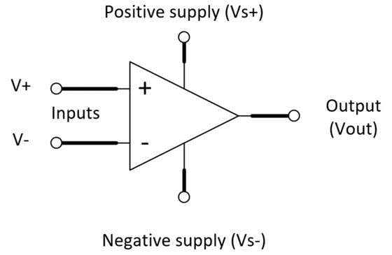 Figure: The above figure shows how an operational amplifier is represented in circuits
What's inside Op-Amp?
The input stage is a differential amplifier. The differential amplifier used as an input stage provides differential inputs and a frequency response down to DC (To learn about differential amplifiers, Click here). Special techniques are used to provide the high input impedance necessary for the operational amplifier. The second stage is a high-gain voltage amplifier. This stage may be made from several transistors to provide high gain. A typical operational amplifier could have a voltage gain of 200,000 (Gain is a factor that is used to increase the output voltage of the amplifier). Most of this gain comes from the voltage amplifier stage (An intermediate stage that is shown in the below diagram). The final stage of the op-amp is an output amplifier. The output amplifier provides low output impedance. The actual circuit used could be an emitter follower. The output stage should allow the operational amplifier to deliver several milliamperes to a load. Notice that the operational amplifier has a positive power supply (+VCC) and a negative power supply (−VEE). This arrangement enables the operational amplifier to produce either a positive or a negative output. The two input terminals are labeled "inverting input" (−) and "non-inverting input" (+). The operational amplifier can be used with three different input conditions (modes). With differential inputs (first mode), both input terminals are used, and two input signals, which are 180 degrees out of phase with each other, are used. This produces an output signal that is in phase with the signal on the non-inverting input. If the non-inverting input is grounded and a signal is applied to the inverting input (second mode), the output signal will be 180 degrees out of phase with the input signal (and one-half the amplitude of the first mode output). If the inverting input is grounded and a signal is applied to the non-inverting input (third mode), the output signal will be in phase with the input signal (and one-half the amplitude of the first mode output).
Note: Every operational amplifier has the same block diagram as shown below, and it works that same way!!
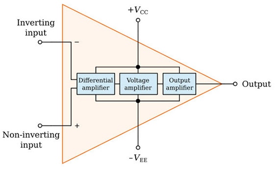 Figure: Block diagram of the Operational Amplifier
IC-741 (Operational Amplifier):
The IC 741, often referred to simply as the 741, is one of the most widely used operational amplifiers in the world of analog electronics. Introduced by Texas Instruments in the late 1960s, the 741 quickly became a staple component in countless electronic circuits due to its versatility, reliability, and affordability. It's a general-purpose operational amplifier, providing high gain and relatively low input impedance. Physically, the 741 typically comes in an 8-pin Dual In-Line Package (DIP), although it's available in various other packages as well. Internally, it consists of multiple transistors, resistors, and other components configured to perform amplification and signal processing tasks.
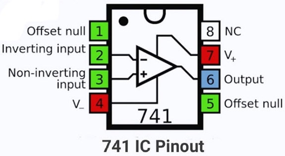 Figure: IC Pinout of an Operational Amplifier IC (741 IC)
The 741 operational amplifier typically comes in an 8-pin Dual In-Line Package (DIP). Here's a description of each pin and its function:
- Pin 1 (Offset Null): This pin is used for offset nulling, which allows fine-tuning the offset voltage at the output. It's often connected to the ground or a small variable resistor for adjustment.
- Pin 2 (Inverting Input): This is the inverting (-) input terminal of the op-amp. The input signal is applied to this pin, and the output voltage is inversely proportional to the voltage difference between this pin and the non-inverting input (Pin 3).
- Pin 3 (Non-Inverting Input): This is the non-inverting (+) input terminal of the op-amp. The input signal is applied to this pin, and the output voltage is directly proportional to the voltage difference between this pin and the inverting input (Pin 2).
- Pin 4 (Negative Power Supply): This pin is connected to the negative terminal of the power supply in single-supply configurations. In dual-supply configurations, it's often connected to ground or a negative voltage source.
- Pin 5 (Offset Null): This pin is another offset nulling pin, similar to Pin 1. It's also often connected to the ground or a small variable resistor for offset adjustment.
- Pin 6 (Output): This pin provides the amplified output signal of the operational amplifier. The output voltage is determined by the input voltages at Pins 2 and 3, as well as the amplifier's internal gain.
- Pin 7 (Positive Power Supply): This pin is connected to the positive terminal of the power supply in both single and dual-supply configurations.
- Pin 8 (No Connection): This pin is not internally connected and is often left unconnected or used for thermal dissipation in some packages.
Despite its widespread use, the 741 does have some limitations compared to more modern operational amplifiers. It has a relatively slow slew rate, limited bandwidth, and is susceptible to noise and temperature variations. However, for many basic applications, these drawbacks are not significant. While newer and more advanced operational amplifiers have been developed since the introduction of the 741, it remains a popular choice for educational purposes, basic circuits, and applications where its characteristics meet the requirements. Its enduring popularity is a testament to its enduring usefulness in the world of electronics.
Conclusion:
In conclusion, operational amplifiers, or op-amps, stand as an important component in the world of analog electronics. Their versatility, high gain, and predictable behavior make them vital tools for engineers, hobbyists, and students. Whether used for amplification, filtering, or signal conditioning, op-amps continue to shape the landscape of electronic design. With their popularity and widespread use, understanding the fundamentals of op-amps opens doors to a world of creative possibilities in circuit design and innovation.
This blog just covered the basics of an op-amp, but there are a lot of things that you should know about an op-amp. To learn more about op-amps, Click Here


