Fundamentals of Radar
2024-12-04 | By Raymond Walker
Introduction:
This is the first of three posts designed to guide you through the powerful capabilities of radar technology and how it can enhance your project’s ability to sense the world around it. The Idea occurred when I asked, “I want an excuse to learn radar, how hard could I be?” The answer is: it’s hard, but hopefully I will take care of some of the work and give the answers to you.
Radar was developed in the early 20th century using radio waves to find information about a target/aim, giving the name “RAdio Detection And Ranging”. Since then, nations use Radar for weather and defense. Radar has found commercial success in the automotive industry, where it is used in virtually all modern vehicles to add additional safety features.
Because of this, radar has become ever more accessible to hobbyists with its reduced size, complexity, and price.
Basic Principles of Radar:
Radar works by emitting a radio wave to a target using a transmitter, where the signal will collide with the target and return an “echo” which is collected using a receiver. Using this echo, lots of information can be processed and used to characterize the target’s speed, distance, altitude, size, and much more.
Radio Waves
The key component of Radar is the use of radio waves to gain information about a target.
These radio waves are produced using an antenna, where an alternating current is used to oscillate an electromagnetic wave, a wave that consists of both an electric component and a magnetic component. The antenna transmits these electromagnetic waves in short bursts, also described as pulses.
This pulse will travel at approximately the speed of light and will remain at that speed unless interfered with by the atmosphere or environment (EM waves move at the speed of light because they are light. The speed of light is found using Maxwell’s Equations which would require an entire blog of its own.) This pulse will then be reflected off a target and an echo will be produced.
(Please note that when I say wave, do not think of it as an ocean wave. A better way to think is that of a sound wave.)
Throughout this series I will be using several terminologies to describe components in this order, some terms will be left to be explained in further sections and are cross-referenced often:
- Frequency and Bandwidth
- Radar Cross Sections
- Pulse Modulation
- Signal Reflection and Scattering
- Doppler Effect
- Attenuation and Propagation
- Noise and Interference
- Polarization
I hope to provide the most understandable presentation of information without losing detail, however, math is unavoidable, and I highly suggest learning about what these formulas mean. At a minimum, plug these formulas into ChatGPT and ask for an explanation.
Frequency Bands and Wavelength

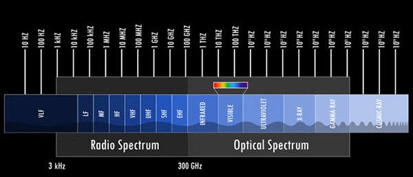
Electromagnetic Spectrum (NASA)

IEEE / NATO RADAR bands (radartutorial.eu)
The electromagnetic spectrum is broken up into several “bands”. A band is a region of the EM spectrum defined by frequency. We are concerned with the region between 3 kHz and 300 GHz defined as the Radio Spectrum. (If you’re wondering what a hertz is, it is a unit of frequency. Frequency refers to the number of cycles per second. In the case of radar, the waves we’re concerned about oscillate between 3000 – 300,000,000,000 cycles per second!) The Radio Spectrum is then categorized (both IEEE and NATO have different categories) and split.
(If you’re curious about how to find wavelength, remember that EM waves move roughly the speed of light, therefore we find that wavelength = speed of light / frequency, or speed of light multiplied by time per cycle or period.)
Each category/band has different responses when emitted and echoed. For instance, lower frequency bands can remain unaffected by environmental disturbances like clouds and mountains. However, these lower frequency bands cannot be as accurate as higher frequency bands.
Radar Cross Section
 A-26 Invader Radar Cross Section (Averse, CC BY-SA 3.0 <http:>, via Wikimedia Commons)
Radar Cross-Section (RCS in m^2 / square meters or unit of area) refers to how well electromagnetic waves interact with an object and create echoes. In the case of aircraft, it may be advantageous to have a large cross-section so that it is easier to detect (Large commercial aircraft in a busy airport typically have a cross-section between 10 – 100 m^2 ) while it’s the opposite if stealth is a priority (stealth planes like the F-35 have a cross-section of just 0.0015 m^2). It should be noted that RCS is an intrinsic property of a target, meaning that it does not change unless the target physically changes.
The cross-section depends on an object: size, shape, and angle to target. The cross-section also depends on the wavelength/frequency of the radar.
We can calculate the RCS of a shape using the formula

RADAR Cross Section
Where σ is the Radar Cross section in m--^2
R is the distance from the radar to the target
Pr is the power density of the radar wave echoed from the target
Pt is the power density of the radar wave emitted towards the target
If you are like me, you may look at the formula and look at the previous statement and ask, “If frequency affects RCS, why is it not in the formula?”
The reason is that frequency determines how the wave reacts to the target while power is the energy emitted and received. Remember back to the frequency section, where frequency is used to help find the target, now we introduce power to help characterize the target.
Pulse Modulation

Pulse Modulation helps make collecting data from pulses easier by controlling the pulse itself.
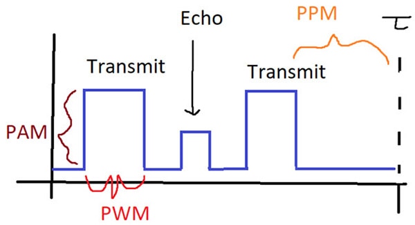
The pulse can be changed in three ways: pulse width modulation (PWM) where the width of the pulse is changed, pulse position modulation (PPM) where the position of the pulse is changed in a period, or pulse amplitude modulation (PAM) where the amplitude is changed.
These techniques are used to help clarify returns; a good example is if pulses are being created too frequently, we could lose track on which pulse causes an echo. Pulses could also be modulated to help increase or decrease the power of a pulse to remove noise or get a better return.
Signal Reflection and Scattering
This entire series has been written using the words “echo”, “return” or “return signature”. These are all in reference to the radio wave reflecting off a surface. These reflections are called “back scatter” and are used to calculate range, speed, and direction of the target.
The reflections are dependent on the angle the target is from the radar, the material of the target, and the environment around the target.

Doppler Effect

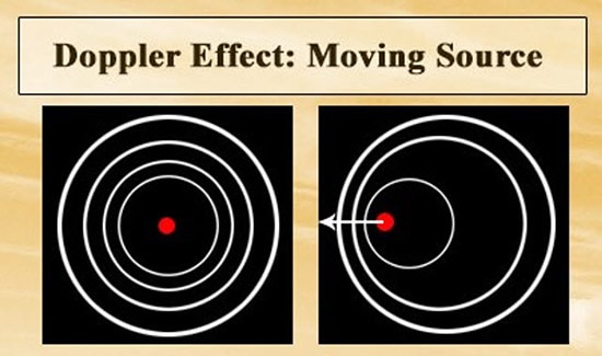
(Zappys Technology Solutions’, https://www.flickr.com/photos/102642344@N02/15038818363)
A good introductory example of the Doppler effect is an ambulance siren. When the ambulance is approaching you, the sound waves have a higher pitch as they have a higher frequency. When the ambulance passes you, the sound becomes duller and more distant as the frequency decreases. Using what we know from signal reflections, the waves will be altered by the Doppler effect. Using these altered waves, we can process the wave and use the changes to draw information about a target such as speed.
The formula to calculate speed is:

Where
v = speed of target
f¬r = frequency of the reflected wave
ft = frequency of the transmitted wave
c = speed of light
Attenuation and Propagation
Attenuation refers to the reduction of power in a radar wave. As mentioned in the signal reflection section, emitted signals can be interfered with by the environment, material of the target, or even “destructive waves” (waves that cancel the amplitude of the radio wave). As also mentioned in the Doppler effect, as a wave moves farther away from the signal the frequency slows down, also attenuating the signal.
Propagation refers to how the radar signal behaves as it is emitted towards the target and is then reflected. Propagation is affected by:
- Line of sight to target
- Quality of reflection
- Refraction (bending or change in direction of the wave)
- Diffraction (waves bending from a sharp edge)
- Multipath propagation (several diffracted, refracted, or direct signals returning to the receiver)
Both attenuation and propagation can affect a radar system's accuracy and are important to be aware of.
Noise and Interference
Noise is unavoidable as it is caused by thermal noise/heat, atmospheric noise, or even receiver noise from the several semiconductor devices inside the receiver.
The value used to determine the effect on the radar system is the signal-to-noise ratio, where the higher the value the clearer the signal.
When noise becomes large enough, the detection range and accuracy become severely degraded.
Interference refers to other signals obstructing the radar’s performance. Luckily, interference can be more predictable than noise.
Interference can be caused by other radars, communication systems like phones or televisions, and electronic devices like microwaves or routers.
This interface can occur on a co-channel basis (same frequency) or adjacent (nearby frequency channels).
Interference can cause a radar to detect false targets, give false information about real targets, or cause overall performance degradation.
We can minimize the effects by:
- Filtering noise and interference
- Frequency hop by changing the operating frequency
- Pulse compression (refer back to modulation) to improve signal-to-noise ratio
- Shielding and grounding to minimize environmental noise
- Adaptive algorithms: using algorithms to adjust the radar to noise and interference
Polarization
Polarization refers to the orientation of the electromagnetic waves as they are emitted. We can use polarization to help minimize interference/noise while improving signal. It should be noted that if the emitted polarization does not match the polarization of the target, the received signal will be reduced.
Polarization can affect the wave in several ways:
- Horizontal polarization where the electric field is oriented in the horizontal direction
- Vertical polarization where the electric field is oriented in the vertical direction
- Right-hand circular polarization where the field rotates in a “right-hand” helix
- Left-hand circular polarization where the field rotates in a “left-hand” helix
- Elliptical polarization where the field could be both vertically and circularly polarized in the shape of an ellipse
Final Thoughts
I hope you now feel more well-versed in the world of radar. The objective of this tutorial was to help you understand what you can expect when working with radar devices, and how to apply them. In the next part we will begin to talk about hardware and the algorithm/system these radars use to help turn pulses of electromagnetic waves into consumable data.
To help further you’re understanding I recommend reading from these sites:
https://www.ll.mit.edu/outreach/radar-introduction-radar-systems-online-course

Have questions or comments? Continue the conversation on TechForum, DigiKey's online community and technical resource.
Visit TechForum


 中国
中国