How To Use a Multimeter
2023-07-12 | By Maker.io Staff
Another recent article explained multimeters and the characteristics makers should consider when buying one of these must-have gauging devices. This article, however, will explain the basics of operating a standard digital multimeter and how to measure common physical properties most of us will find helpful when diagnosing circuits in our projects.
The Parts of a Multimeter
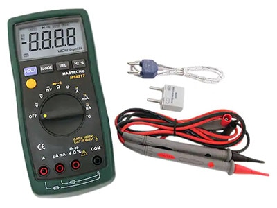
Before measuring, you should familiarize yourself with your newly acquired equipment. While most devices will slightly differ from other multimeters available for purchase, they typically all share some standard features, as illustrated by the following image:
 This figure explains the main parts of a common handheld multimeter.
The main display, which might be either a more straightforward LCD or a more complex full-color readout, shows the current measurement results. The hold button locks the currently displayed value for later reference. Some meters may also include memory and recall buttons to store a few readout values. The function selection dial allows you to select which physical property to measure. Finally, the probes plug into the ports, depending on the property to measure. However, there’s typically a common ground port for all functions. Note that some meters may include different probes, such as alligator clips, or they may not have any probes.
Using a Multimeter to Measure Voltage
Start by plugging the black probe into the common port and the red probe into the voltage port on the meter to measure the voltage in a circuit or across a component:
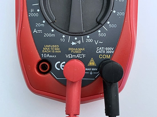 Plug the probes into the multimeter’s voltage measurement port, as indicated by the markings on the device.
Note that switching the red and black probes will not cause any harm. This will, however, negate the result shown on the screen, as the meter always measures the voltage relative to the common probe. Either way, use the function selection dial next to switch the meter into voltage mode. Make sure to choose DC or AC mode, accordingly:
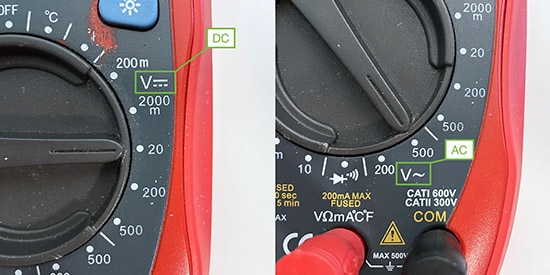 Note the markings next to the numbers to switch between AC and DC measuring.
When measuring voltage, always measure the voltage in parallel. Essentially, in order to gauge ;the voltage across a component, you place one of the probes on each of the component’s legs. Similarly, when determining the potential difference between two traces in a circuit, each lead needs to be connected to one of the traces. The circuit does not need to be opened in order to determine the voltage:
This diagram illustrates how to measure the voltage between the two resistors, R1, and R2. (Use the tabs at the bottom to select the various circuit diagrams)
Finally, note that when measuring any physical size with a multimeter, the value on the dial indicates the maximum value. Selecting 200 V, for example, allows measuring voltages of up to 200 V. It’s advisable not to massively overshoot the actual voltage in the circuit, however, as larger limits tend to deliver less accurate results. When the real value is unknown, start with the largest value on the dial and work your way down to determine the true value.
Measuring the Resistance
Measuring the resistance of a component is very similar to determining the voltage differential between two points. Start by connecting the probes as shown above, and then select the ohmmeter setting with an appropriate range on the multimeter:
 Make sure to switch the meter into resistance mode and choose an appropriate upper limit.
Then, measure the resistance across a component in parallel:
This diagram illustrates how to measure the total resistance of the circuit. (Use the tabs at the bottom to select the various circuit diagrams)
Finding Open and Short Circuits Using a Multimeter
Most multimeters can also help you find short and open circuits in your projects. A short circuit occurs when there’s an electrical connection that shouldn’t be present, while an open circuit describes the state where there’s a missing or bad connection between two components that should be connected. In either case, a multimeter can determine these problems by measuring resistance. Very low resistance indicates a short circuit, while very high resistance points toward an open circuit. Start by switching the meter into continuity mode, which is often denoted by a symbol similar to the one shown in the following image:
 Look for a marking similar to the one outlined in this picture to switch the meter into continuity mode.
Then, place the two probes on the two points of the circuit that should or shouldn’t be connected, keeping in mind that the order of the probes doesn’t matter. The meter will then make a beeping sound when the two points are electrically connected. Otherwise, it will remain silent.
Measuring the Current in an Electric Circuit
Multimeters typically also measure the electric current that flows through a circuit. Until now, the meter was always used in parallel to the components of interest. Yet when determining the current, the meter must be placed in series with the point of interest in the circuit so that the current flows through the meter. To use a water pipe analogy: The water must flow through the measuring device to measure the water flow through a pipe.
Some meters may require plugging the red probe into a dedicated port for current measurements. However, the particular meter used throughout this article supports two modes — a fused one for up to 200 mA and an unfused mode for measuring currents of up to 10 A.
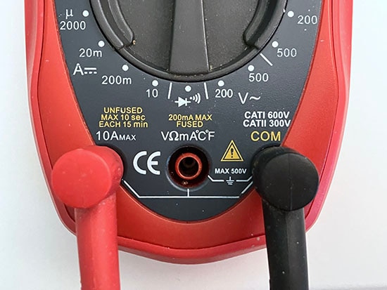 Make sure to plug the probes into the correct port when measuring current.
Note that measuring too high an amperage in the fused mode will blow the protective fuse in the multimeter. In that case, the fuse must be replaced before the meter can make any other fused amperage measurements.
Once done selecting the mode, open the circuit that needs to be tested and place the multimeter’s leads in series so that the probes close the circuit, as shown in the following diagram:
Placing the multimeter as shown allows measuring the current flow through the entire circuit. (Use the tabs at the bottom to select the various circuit diagrams)
Summary
Multimeters are essential to every maker’s toolbox, as they allow you to troubleshoot circuits in many different ways. This article discussed how to measure the voltage across components, the resistance of parts, and the current flow through a circuit.
To summarize, measure voltages, resistance, and continuity parallel without opening the circuit. In contrast, measuring the current must happen in series so that the meter closes the previously open circuit.
When measuring currents, make sure not to overload the meter. Doing so will blow a fuse, which must then be replaced before performing any other current measurements.
Recommended Reading
What are CAT (Category) Safety Ratings in Multimeters? - Another Teaching Moment | DigiKey


