An Introduction to 14-Segment LED Displays with the HT16K33 Driver
2022-01-17 | By Maker.io Staff
Many hobbyists know and use seven-segment displays in their projects. And while those can be a handy addition to many devices, they can’t display all alphanumeric characters. Therefore, seven-segment LED screens are appropriate for displaying numbers. For more complicated applications, we can resort to using 14-segment displays. This article looks at 14-segment displays and an HT16K33 breakout board that allows you to add these more advanced displays to your projects in practically no time.
A First Look at the HT16K33 I2C Breakout Board
The HT16K33 is a multi-function LED controller driver with a broad range of applications. Like the MAX7219, another popular LED controller IC, you can employ the HT16K33 in many projects and scenarios. Example use-cases include LED matrices and seven-segment displays. However, the HT16K33 is also capable of driving and controlling more sophisticated 14-segment displays. Such LED displays allow your projects to output alphanumeric characters rather than just one-digit numbers. The HT16K33 communicates via I2C, which ensures that you can employ it in pretty much every microcontroller-driven project without implementing a complicated proprietary communication method.
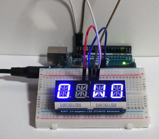
 The HT16K33 backpack in action. The Arduino executes a small demo program that displays a string on the display.
Connecting the HT16K33 14-Segment I2C Breakout Board to an Arduino
As noted above, the HT16K33 uses I2C to communicate with an external microcontroller. The MCU can send commands to the controller to output alphanumeric characters using the four 14-segment displays this breakout board supports. Therefore, you only need to make four connections between your Arduino and the 14-segment display board:
 You only need to make four connections between the Arduino and the HT16K33 breakout board.
This breakout board allows you to use up to eight 14-segment modules with a single Arduino and without external components. You can change each display’s I2C address using the three jumper pads on the bottom side of the PCB.
 You can use these three solder pads to change the I2C address of a module. The three pads allow you to control up to eight 14-segment breakout boards with a single Arduino.
Use an Arduino to Send Characters to the 14-Segment Display
Once you’ve connected the power and I2C lines between the Arduino and the HT16K33 breakout module, it’s time to write an Arduino program that transmits data to the HT16K33, which then takes care of displaying the information on the four 14-segment LED displays.
Start by downloading the Adafruit LED Backpack and Adafruit GFX libraries using the Arduino IDE’s built-in library manager. You can have a look at this article if you don’t know how to install libraries using the Arduino IDE.
 Download the Adafruit LED Backpack and Adafruit GFX libraries using the Arduino IDE’s built-in library manager.
Then, you can import and use the library in your custom Arduino programs. The following sketch displays a string using the 14-segment displays attached to the Arduino:
#include <Wire.h>
#include <Adafruit_GFX.h>
#include "Adafruit_LEDBackpack.h"

#define DISPLAY_ADDRESS 0x70

Adafruit_AlphaNum4 disp = Adafruit_AlphaNum4();

String text_to_display = "  HELLO WORLD  ";
int string_pointer = 0;
char display_buffer[4];
long last_display_refresh = 0L;

void setup()
{
  disp.begin(DISPLAY_ADDRESS);
  disp.setBrightness(4);
  disp.clear();
  disp.writeDisplay();
}

void loop()
{
  long current_millis = millis();

  if(current_millis - last_display_refresh > 300)
  {
	if(string_pointer >= text_to_display.length())
  	    string_pointer = 0;

	// Move the existing characters one position to the left
	for(int u = 0; u < 3; u++)
  	    display_buffer[u] = display_buffer[u + 1];

	// Replace the right-most character with the next
	// character from the text_to_display variable
	display_buffer[3] = text_to_display.charAt(string_pointer++);

	// send the text to the display
	for(int i = 0; i < 4; i++)
  	    disp.writeDigitAscii(i, display_buffer[i]);

	// display the text
	disp.writeDisplay();

	// update the timing variable
	last_display_refresh = current_millis;
  }
}
In the short Arduino sketch above, the loop()-function does most of the work. But first, the setup()-function initializes the 14-segment display, reduces its brightness, and clears it. Then, the loop function checks whether 300 milliseconds have elapsed since the last update. If that's the case, the Arduino sketch updates the displayed text.
When updating the text, the sketch checks whether it has reached the end of the string. If that’s the case, the Arduino resets the pointer to reference the first character. Next, the update()-function moves each previously displayed character one spot to the left and fills the fourth position with the next character from the string. Then, the sketch sends the new character data to the 14-segment display. Lastly, the program instructs the HT16K33 controller to print the characters on the screen. These steps result in a simple scrolling text display.
Summary
Seven-segment LED screens are perfect for displaying simple numeric values. However, you can't use them to output most alphanumeric characters. 14-segment LED screens can display all 26 Latin characters as well as numeric values. Therefore, you can use them in your projects to supply users with more detailed status messages and error descriptions, for example.
The HT16K33 is a popular and simple to use LED matrix controller similar to the MAX7219. An external device such as an Arduino UNO can communicate with the HT16K33 via I2C. A simple-to-use Arduino library allows you to get started with 14-segment displays almost instantly.

Have questions or comments? Continue the conversation on TechForum, DigiKey's online community and technical resource.
Visit TechForum


 中国
中国