How to Add a Keypad to an Arduino Project
2021-03-17 | By Maker.io Staff
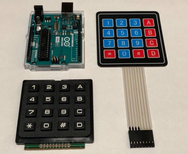
There are numerous ways for users to make inputs in Arduino-based projects. You can choose from simple input methods, like momentary push buttons, to more elaborate approaches. This article discusses keypads, which are a more advanced method to allow users to interact with an Arduino. It explains how to connect a small keyboard to an Arduino, how the keypad functions in theory, and how you can implement that theory in software.

BOM
Part/Where to buy
How a simple keypad works
Simple keypads and keyboards without a dedicated controller typically work in an easy-to-understand way. You can divide the keypad into rows and columns as follows:

Note how the buttons sit exactly where the rows and columns meet. The Arduino, or any other microcontroller, sends a quick pulse to each line, one row at a time. In this article, the Arduino pulls the input lines low for a short period. It then checks whether any of the columns transitions to a low state as well. If that happens, the Arduino registers a button press. Suppose that a user presses the five-key on the keypad. The Arduino pulls each of the yellow input lines low. When it reaches the second yellow line, it detects that reading the second column returns a low state. That happens because someone pushes a button. Each button connects a row and a column, just like an ordinary switch.
Connect a keypad to an Arduino
Luckily, it is much easier to connect a keypad to an Arduino than it seems at first glance. You only need eight digital I/O pins for that task:
I used the same color scheme as in the image above. The green connections correspond to the columns, and the orange ones represent the rows. Note that these simple keypads don’t require power to operate. They act like an array of simple switches. Note that this setup doesn’t require external pull-up or pull-down resistors, as the sketch will enable the internal pull-up resistors of the Arduino.
Reading button presses with an Arduino sketch
The following code allows an Arduino to detect key presses on a keypad. It implements the line and column method discussed above:
#define L1 9
#define L2 8
#define L3 7
#define L4 6

#define C1 5
#define C2 4
#define C3 3
#define C4 2

void setup()
{
  Serial.begin(9600);

  pinMode(L1, OUTPUT);
  pinMode(L2, OUTPUT);
  pinMode(L3, OUTPUT);
  pinMode(L4, OUTPUT);
  pinMode(C1, INPUT_PULLUP);
  pinMode(C2, INPUT_PULLUP);
  pinMode(C3, INPUT_PULLUP);
  pinMode(C4, INPUT_PULLUP);

  digitalWrite(L1, HIGH);
  digitalWrite(L2, HIGH);
  digitalWrite(L3, HIGH);
  digitalWrite(L4, HIGH);
}

void loop()
{
  readLine(L1, "123A");
  readLine(L2, "456B");
  readLine(L3, "789C");
  readLine(L4, "*0#D");

  long m = millis();

  while(millis() - m < 500);
}

void readLine(int line, String characters)
{
  digitalWrite(line, LOW);

  if(digitalRead(C1) == LOW)
	Serial.println(characters.charAt(0));
  else if(digitalRead(C2) == LOW)
	Serial.println(characters.charAt(1));
  else if(digitalRead(C3) == LOW)
	Serial.println(characters.charAt(2));
  else if(digitalRead(C4) == LOW)
	Serial.println(characters.charAt(3));

  digitalWrite(line, HIGH);
}
The “define” statements at the beginning of the file correspond to the lines and I/O pins mentioned above. The setup method initializes all I/O pins and pulls the output pins high. This example uses negative logic to allow the circuit to function without external pull-up or pull-down resistors. So, instead of sending a high pulse, the Arduino sends a low pulse to the keypad and listens for a low state on one of the column lines to identify key presses. This detection happens in the readLine method. It sends that pulse to a given output pin and checks each input pin. As soon as the Arduino detects that one of the inputs is low, it prints the name of the detected key to the console. The loop method calls the readLine function for each of the four lines on the keypad before it waits for 500 milliseconds. Note that this code doesn’t implement any de-bounce prevention, and it also doesn’t detect if a user holds down a button over a prolonged period.
Summary
Adding a keypad to an Arduino-powered project is almost as simple as connecting a simple LED. This method, however, gives users an intuitive and easy way to interact with an Arduino. Any microcontroller can detect key presses on a keypad by pulling each line high or low and then checking each row for changes. Each button on the keypad connects a column to a row, and when a user presses a button, the Arduino can detect changes on the input pins and map them to the individual buttons on the keypad.

Have questions or comments? Continue the conversation on TechForum, DigiKey's online community and technical resource.
Visit TechForum


 中国
中国