How to Communicate Between Arduino Boards and Raspberry Pi SBCs
2020-07-29 | By Maker.io Staff
Hobbyists, makers, developers, and professionals can choose from a wide variety of different development boards, single board computers, and edge computing platforms.
All of these platforms have different specifications, features, and performance requirements. Thus, complex systems often use multiple platforms in conjunction to execute various sub-tasks.
This article discusses the most important standard communication protocols involved in establishing communication between different platforms like Arduino, NodeMCU/ESP32/ESP8266, Raspberry Pi, Jetson, Nucleo, and a PC. NodeMCU, ESP32, and ESP8266 belong to the same family of Wi-Fi-enabled microcontrollers but feature subtle differences.
BOM
- Raspberry Pi 3
- Arduino Nano
- Arduino Mega
- Arduino Uno
- Jetson Nano
- USB A-B Cable
- ESP32 DEVKIT
- Male-Female, Male-Male, Female-Female Jumper Wires
- Breadboard
Common Communication Protocols
Communication protocols define a set of rules, hardware requirements, and specifications for data exchange between multiple systems. For any electronic circuit, data moves around through voltage signals disguised as electromagnetic (EM) waves. Electric current is the only physical quantity it can measure. The methods by which the voltage signal and its transmission frequency are modulated define the physical value for the data as digital or analog or several variations of the two.
Communication protocols have two crucial aspects - the connection between devices and the data exchange specifications. Dedicated circuitry-based mechanisms including USART, SPI, and I2C are commonly available simultaneously on maker boards, while common commercial connection mechanisms such as Ethernet, USB, Bluetooth, and Wi-Fi are not.
USART stands for Universal Synchronous Asynchronous Receiver Transmitter and is a serial communication protocol that transfers data bit by bit with clock pulses for synchronization over two wires, Rx and Tx. UART is the asynchronous mode for USART and does not carry a clock pulse.
Serial communication can happen over the RS-232, RS-422, and RS-485 protocols that define the electrical characteristics of the signals to be transferred over the UART ports.
Inter-Integrated Circuit, referred to as I-squared-C, (I2C) communicates between peripherals and dev boards over two wires (SDA (serial data wire) and SCL (serial clock line)). It is a master-slave bidirectional communication strategy that supports multiple slaves and can be multiplexed.
Serial Peripheral Interface (SPI) is a 4-wire (MOSI (Master Output Slave Input), MISO (Master Input Slave Output), SS (Slave Select), and SCLK (Serial Clock)), full-duplex serial communication protocol. It uses the master-slave configuration to communicate on a preconfigured frequency at very high speeds. A slave is identified by an ID and a master can communicate with only one at a time.
Controlled Area Network (CAN) is a 2-wire CAN High H+ and CAN Low H-, full-duplex serial communication protocol. It supports multi-master configuration and helps devices communicate without the need of a host machine.
Arduino Uno with Raspberry Pi, Laptop/PC, or Jetson
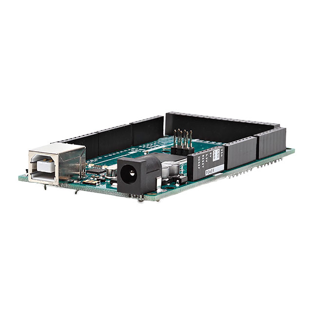
It’s common to see the serial output of an Arduino in the IDE that runs on a computer. Users can, however, also utilize this technique to communicate with other development boards. Any board or computer with a full-size USB A host connector can be connected to the Arduino with the help of a USB-A to USB-B cable. The communication takes place over the serial port (USART/UART). In this setup, the Arduino board handles the logic-level conversion itself. In order to facilitate the digital pins 0 (RX) and 1 (TX), an external TTL logic level converter board is required.
The program in Listing 1 shows how to utilize the serial port of an Arduino Uno to send data over its serial interface. The python program in Listing 2 runs on the other computer or board and receives the messages that the Arduino transmits. An extension of these examples easily allows for bidirectional communication:
int count = 0;

void setup() {
  // initialize serial:
  Serial.begin(9600);
}

void loop() {
  if (count%10 == 0) {
    Serial.println("Hello, Serial communication works");
  } else {
    Serial.println(count);
  }
  count++;
}
Listing 1: Arduino Uno code for serial communication
import serial, sys
from serial import SerialException
#  Install using pip3 install --user pyserial

if __name__ == "__main__":

    serial_comm = serial.Serial()

    # Configure the baud rate and it should be equal to the Arduino code serial communication baud rate
    serial_comm.baudrate = 9600

    # Configure the COM port as needed '/dev/ttyXXXX' is applicable for Linux systems
    serial_comm.port = '/dev/ttyACM0'

    #Configure timeout seconds
    serial_comm.timeout = 10

    try:
        serial_comm.open()
    except serial.SerialException:
        # Print an error when the serial communication isn't available
        print ("Could not open port")

    while (True):
        if serial_comm.isOpen():
            print ("Serial Incoming Data: {}".format(serial_comm.readline()))
        else:
            print ("Exiting")
            break
    sys.exit()
Listing 2: Python Code for serial communication
I2C - Arduino Uno with Arduino Uno, NodeMCU/ESP32/ESP8266, Nucleo, Jetson, or Raspberry Pi
Users can connect an Arduino Uno to any other development board that supports communicating over the I2C bus. Furthermore, it’s possible to connect two arbitrary devices with I2C capabilities and make them interact in a master-slave configuration. On the software side, there are several libraries for different programming languages available that facilitate this interface.
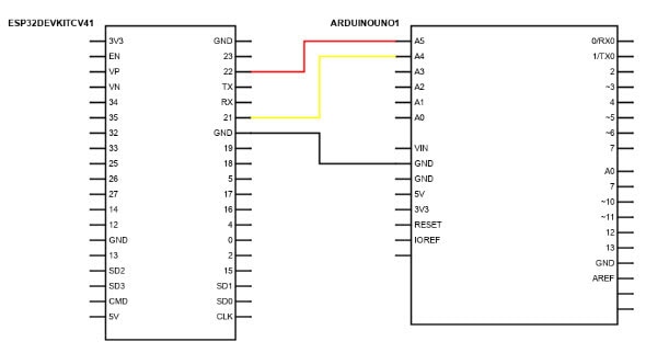
An Arduino Uno can be connected to the ESP32 DEVKIT using GPIO pins as shown in Figure 1. The Arduino will act as the slave, while the ESP32 takes the role of the master device. It's easy to port the code from Listing 3 and 4 to execute it on NodeMCU and other ESP8266 boards. Make sure, however, to use the appropriate I2C communication pins on every platform.

Figure 1: Arduino Uno (Slave) with ESP32 (Master) for I2C communication
#include <wire.h>
void setup() {
  // D2(SCL) and D1 (SDA) for NodeMCU I2C Communication
  // 22(SCL) and 21 (SDA) for ESP32-DEVKITC V4 (USED HERE) I2C Communication
  Wire.begin(21, 22);
}

void loop() {
  // Begin transmission with device address 8
  Wire.beginTransmission(8);
  Wire.write("ESP32- DevKitC V4 to Arduino");
  // End transmission
  Wire.endTransmission();
  delay(100);
}
</wire.h>
Listing 3: NodeMCU/ESP32/ESP8266 code for I2C communication
#include <wire.h>
void setup() {
// Start communication over I2C bus with address 8
Wire.begin(8);
// Callback for I2C data receive event
Wire.onReceive(dataReceiveEvent);
// Callback for I2C data request event
Wire.onRequest(dataRequestEvent);
// Serial communication to visualize data received in Arduino IDE Serial Monitor
Serial.begin(9600);
}
void loop() {
delay(100);
}
// Callback function when data is received from the master
void dataReceiveEvent(int received_bytes) {
while (Wire.available()) {
// Receive data per byte
char c = Wire.read();
// Print to serial port for visualization
Serial.print(c);
}
Serial.println();             /* to newline */
}
Listing 4: Arduino Uno code for I2C communication
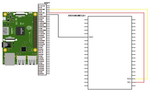
A Raspberry Pi 3 and an Arduino Mega connect as shown in Figure 2, allowing them to communicate over I2C. The RP3 does not have an Arduino IDE environment for libraries, so it requires either a Linux package like i2c-tools running in the terminal or a Python library like python-smbus. A logic level converter is needed because the boards run on different logic levels (Arduino Mega (5 V) and Raspberry Pi 3 (3.3 V)).

Figure 2: Arduino Mega with Raspberry Pi 3 for I2C communication
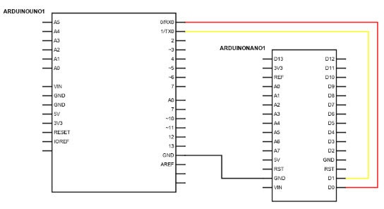
Apart from the I2C bus, Arduino boards can also communicate using the serial interface. For an Arduino Uno to communicate with an Arduino Nano, connect the RX pin of one Arduino to the TX pin of the other board and vice-versa. All other Arduino boards can be connected similarly using the RX/TX pins. For the I2C connection, the SCL/SDA pins need to be connected.

Figure 3: Arduino Uno with Arduino Nano connections for serial communication
All common development boards have a serial communication interface like the UART and I2C communication. Thus, any two boards being discussed here can talk to one another using either of the two strategies. Using I2C communication, many-to-one communication can also be established. The possible communication pairs are an exhaustive list not covered in this article. However, this article gives users an idea of the possibilities.

Have questions or comments? Continue the conversation on TechForum, DigiKey's online community and technical resource.
Visit TechForum


 中国
中国