How To Use the I2C Module on the Particle Photon
2019-05-22 | By Maker.io Staff
Breadboards Wireless Other RF Wifi Photon
When building projects with the Particle Photon, you will eventually need to use hardware more advanced than tactile switches and LEDs. In this tutorial, we will learn how to use the Wire library to interface with I2C devices which will allow you to interface with many different modules including sensors and serial memory chips!
BOM
Scheme-It

I2C Devices
In the past, most integrated circuits used parallel data busses for communication, and these busses would include data lines, address lines (for choosing different devices) and control signals. This use of parallel data and multiple control lines would result in busses having more than 16 wires, which was OK for large motherboards but not so convenient for compact designs such as portable devices.
While serial ports did exist, they were for connecting one device to another and could not handle more than two devices on the same connection. As electronics became more advanced, and with more peripherals being developed, the need for simple bus solutions became apparent. This resulted in the demand for different bus protocols, including I2C, SPI, and CAN.
I2C is a two-wire bus, where one wire carries the clock signal and the other carries data bits. I2C busses operate around a “master-slave” topology: a single master controller (such as a microcontroller or CPU) controls the clock wire and initiates communication with specific peripherals on the bus. Slave devices (such as memory chips and accelerometers) then respond with their data.
The I2C protocol requires that different types of I2C peripherals have different addresses because I2C busses are common when multiple I2C devices connect to the same pair of wires. There are no select lines or enable lines, and devices are chosen by the master sending a special address byte down the data wire. The data and clock lines are referred to as SDA (Serial Data) and SCL (Serial Clock), and both require pull-up resistors (typically 1K). The diagram below shows how I2C devices are connected to the I2C bus.

I2C can be daunting and confusing when trying to “bit-bang” the bus (i.e., use custom code to control the data and clock wires), but, fortunately, most microcontroller platforms have both inbuilt I2C controllers and I2C libraries. To keep things simple, we will look at how to get the Particle Photon to access an I2C serial memory chip.
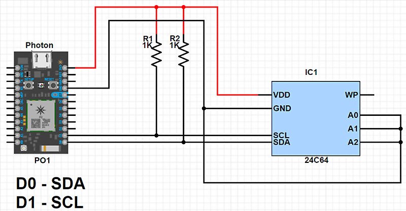
Build the Circuit
The BOM above includes all the parts needed to get us using the I2C module on the Particle Photon, but the I2C serial memory is an optional part (or, to be specific, you just need to use an I2C device). The memory chip is chosen because it also has some external address pins that demonstrate how some identical I2C devices can be connected to the same bus. How the A0-A2 pins are configured will change the control byte that the master sends down the bus when choosing a memory chip.
In our example, we will stick with using the simplest address, “000”, which is done by connecting all address pins to ground (0V). The three address pins (A0 – A2) allow for up to 8 identical memory chips to be connected to the bus, and the table below shows the different addresses possible:

I2C Bus Protocol
An in-depth explanation of the I2C protocol is somewhat unnecessary when using built-in peripherals and libraries, but learning the basics can help in cases when I2C devices refuse to work. A typical I2C transaction involves the following:
- The Master sends a control byte down the bus to choose a specific device
- The Master then sends a command or request for some data
- The Master then sends data associated with that command or the slave device sends data back
- The Master closes the session
Each message sent down a bus is typically 11 bits long, which includes an 8-bit data packet, a start bit, stop bit, and an acknowledge bit. The start bit is the very first bit sent, the 8 bits data packet is then sent, the responding device sends back the acknowledge bit, and then a stop bit is sent.
However, most I2C messages often involve more than one packet of data, so the start bit is only sent at the very start of the transaction and the stop bit is sent at the very end of the transaction (after all the messages have been sent between the master and slave).
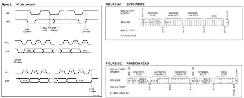
The diagrams below show the I2C protocols for start and stop bits, as well as the messages sent between a master device and a slave serial memory device.

Extracts from 24C01 datasheet and 24C64 datasheet
I2C Memory
When using the Wire library (the library that controls the I2C peripheral on the Photon), the bus protocol itself does not need to be understood, but the control bytes and other data packets that need to be sent to. This is why, when using I2C devices, it’s critical that you read the datasheet, especially paragraphs and diagrams regarding reading and writing.
Serial memory devices have multiple commands and multiple reading/writing techniques, but we will only learn how to do two basic tasks: random read and random write. Random read and random write allow us to write a byte of data into a specific memory address, and this is the most likely type of reading/writing you will do to serial memory devices.
Any communication with an I2C device first requires that a special control byte is sent. In the case of I2C serial memory, this byte is 1010, then the address pin configuration, and then a read/write bit. The extract below shows how the control byte is organized. In our case, the address pins were all connected to 0V, which means our control byte is either 10100000 for writing to the EEPROM or 10100001 for reading from the EEPROM.

Once the control byte has been sent, we then need to either write or read data to/from the I2C memory chip. Writing data to a memory location is very simple and only requires us to send one control byte (write), two address bytes that point to the memory location we wish to save to, and then the data byte that we want to store in that location.
Reading, however, is a little more complex, because we first need to write the memory address that we wish to read from first. This means that we first send the control byte for writing, followed by the address location. Then we send another start bit, followed by the read command, and then read a byte from the I2C device.
Let’s summarize what we’ve covered so far:
Write a byte of data to a memory address
- Send control byte (10100000)
- Send upper address byte
- Send lower address byte
- Send data byte and end
Read a byte of data from a memory address
- Send control byte (10100000)
- Send upper address byte
- Send lower address byte
- Resend start bit
- Send control byte (10100001)
- Read byte and end
Wire Library
With all the theory and protocols touched on, it’s time to see how to use the Wire library! The first line that you will need to include on the top of your code is the library include, shown below:
// I2C Library
#include <Wire.h>
When an I2C transmission is to be started, the function Wire.beginTransmission(controlByte) is called where the control byte is passed as a parameter.
Wire.beginTransmission(B10100000); // Write control byte to I2C memory device at 000
When a byte is to be written to an I2C device, the function Wire.write(byte) is used.
Wire.write(0x10); // Write hex value 0x10 to I2C device
Reading data from I2C devices is not as trivial and requires the use of two functions: Wire.requestFrom(controlByte, numberOfBytesToRead) and Wire.read() . Interestingly, the use of this function automatically sends the control byte with the read bit set and reads n number of bytes (where n is the second parameter in the function). When all the bytes have been read, they are accessed individually using the .read() function, which returns a single byte. The example below shows how to read 6 bytes from an I2C device.
Wire.requestFrom(B10100000, 6);			// Read 6 bytes from an I2C memory device

// Do this loop 6 times to read each byte and store into an array
for(int i = 0; i < 6; i ++)
{
	dataBuffer[i] = Wire.read();		// Pop a single byte from the I2C buffer
}
Once all data has been exchanged, the function Wire.endTransmission() is called. If a restart bit is needed instead, false can be passed to this function.
Wire.endTransmission();				// Send a stop bit
Wire.endTransmission(false);			// Send a restart bit
All of the code above can be combined to give us two main blocks of code that can be used to read and write bytes to and from specific memory address.
// Write a byte to memory location (memoryHigh | memoryLow) 16 bit address
Wire.beginTransmission(B10100000);		// Write control byte to I2C memory device at 000
Wire.write(memoryHigh);				// Memory upper address as byte
Wire.write(memoryLow);				// Memory lower address as byte
Wire.write(dataByte);				// Data to store at address
Wire.endTransmission();				// End the transmission


// Read a byte from memory location (memoryHigh | memoryLow) 16 bit address
Wire.beginTransmission(B10100000);		// Write control byte to I2C memory device at 000
Wire.write(memoryHigh);				// Memory upper address as byte
Wire.write(memoryLow);				// Memory lower address as byte
Wire.endTransmission(false);			// Send a restart bit
Wire.requestFrom(B10100000, 1);			// Request a single byte (read data)
Wire.endTransmission();				// End the transmission
dataByte = Wire.read();				// Read the received data byte

Have questions or comments? Continue the conversation on TechForum, DigiKey's online community and technical resource.
Visit TechForum


 中国
中国