How-To Build a Motion Detection LED Design
2019-02-04 | By Maker.io Staff
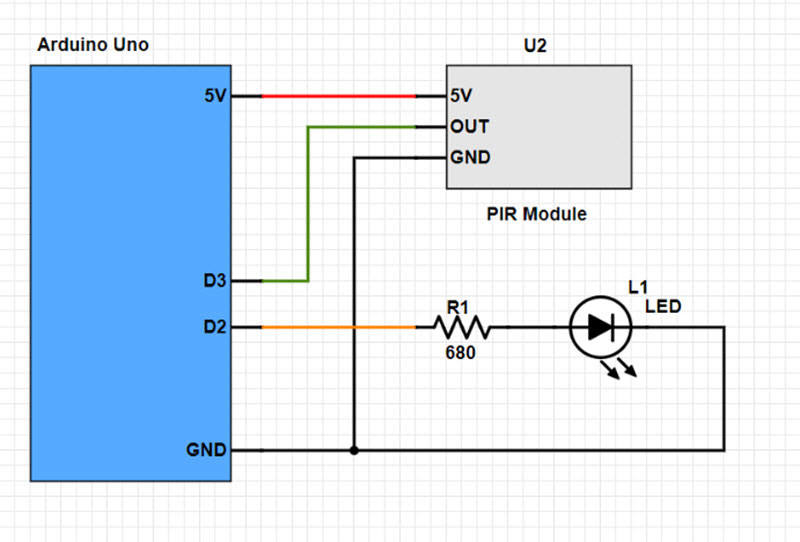
Motion detection using PIR modules is very easy to do thanks to the simple digital output and ease of Arduino programming. In this simple How-To article, we will learn how to make an LED light up when a user walks past an Arduino.
BOM
SchemeIt

https://www.digikey.com/schemeit/project/makeriomotionled-1HPHP4G402C0/
PIR Modules
When it comes to motion detection, there are a number of ways to accomplish this. One method would involve the use of ultrasonic modules that constantly make distance measurements, and if two distance measurements have a substantial difference, then an object must have moved position. However, it may be more appropriate in a scenario to only specifically detect the presence of humans as opposed to inanimate objects.
While this could be achieved with some clever object tracking software, it would be far simpler to use a PIR module. A PIR module, or Passive InfraRed, is a module that houses a pyroelectric sensor to detect levels of heat in an area. Typically, a pyroelectric sensor measures the average temperature of the surrounding environment but this measurement is not particularly useful when trying to track motion.
If an area heats up during the day and cools down during the night then some software is required to constantly take measurements and then account for these cycles. Instead, PIR motion sensors split pyroelectric sensors into two halves that each measure the environment and are connected such that they cancel each other out. When a warm body (remember, humans emit IR radiation in the form of heat) passes the sensor, there is an imbalance between the two sensors and therefore the output of the sensor changes.
In our circuit, we take advantage of the Adafruit PIR Motion Sensor module which not only handles the complex circuitry, but also provides two potentiometers so the PIR module can output pulses at varying length and delay. In this project, these potentiometers are not needed but they could be implemented to provide a delay that is long enough for an authorized user to enter a silence command to prevent an alarm from sounding.
The Arduino
This project technically does not need an Arduino to make an LED turn on during the detection of motion as the LED could directly be connected to the PIR module. However, connecting a module to an Arduino has a number of advantages including the ability to provide custom LED sequences, ability to ignore incoming signals under certain conditions, as well as being able to further process the data.
For example, the LED could be made to flash x number of times, where x is the number of times the PIR sensor has detected the presence of a person.
The Code - Simple
The first step in our code is to configure the pin D2 as an output (for the LED) and D3 as an input (for the PIR sensor). With these configured we then set the variable flashNumber to 0 which is used to flash the LED n number of times whereby n represents the number of PIR detections.
Then in the main code loop, we wait until the PIR output goes high, indicating a detection. When a detection is made the software increments the flashNumber counter and then flashes the LED that number of times. int flashNumber = 0;
int flashNumber = 0;
void setup()
{
pinMode(2, OUTPUT); // LED on pin D2 as output
pinMode(3, INPUT); // PIR module on pin D3 as input
}
void loop()
{
// If the PIR output goes high do stuff!
if(digitalRead(3))
{
// Increment the flashNumber
flashNumber ++;
// Flash the LED flashNumber of times
for(int n = 0; n < flashNumber; n ++)
{
digitalWrite(2, HIGH);
delay(300);
digitalWrite(2, LOW);
}
// Wait for the signal to fall back to 0V
while(digitalRead(3));
}
}
The Code – Interrupt Based
If the PIR module was being used in a more critical situation (such as guarding possessions) then an interrupt may be a better solution. Unlike pin scanning, interrupts execute a section of code as soon as a signal is detected and will interrupt any other code currently being executed so long as that code is not also interrupted code. Therefore, we can adjust our code for this project to include interrupts!
int flashNumber = 0;
void isr_routine(void);
void setup()
{
pinMode(2, OUTPUT); // LED on pin D2 as output
pinMode(3, INPUT); // PIR module on pin D3 as input
the code- interrupt based
// Create an interrupt that only fires on a RISING input on D3
attachInterrupt(digitalPinToInterrupt(3), isr_routine, RISING);
}
void isr_routine(void)
{
// Increment the flashNumber
flashNumber ++;
// Flash the LED flashNumber of times
for(int n = 0; n < flashNumber; n ++)
{
digitalWrite(2, HIGH);
delay(300);
digitalWrite(2, LOW);
}
}
void loop()
{
// Your code here!
}


