制造商零件编号 2N3904BU
TRANS NPN 40V 0.2A TO-92-3
onsemi
We have learned about the different types of motors and what applications they are commonly found in. In this How-To article, we will learn what H-bridges are and why they are needed for DC brushed motors.

DC Brushed Motors, as we know come in many shapes and sizes and are one of the cheapest types of motors to produce. While internal configurations for these motors can vary between designs, the most common type used in maker applications has two permeant magnets surrounding the main stator, which has copper wire coiled around it. These coils connect to a commutator that connects to the main pair of connectors via brushes.
If you look at the back of these motors, you will often see a small polarity symbol next to one of the motor inputs. While this may appear to be an indicator of which way the power must be applied, it is instead an indicator of how the motor will rotate when that polarity is applied. The direction which your motor turns depends on the manufacturer, but in our case, the motor will turn clockwise (when looking from the back) when the + input is + relative to the other input. If the input polarity is reversed, then the motor turns the opposite direction.
So, by flipping the polarity to the motor, we can make it go backward and forward, but how do we implement this in circuitry?
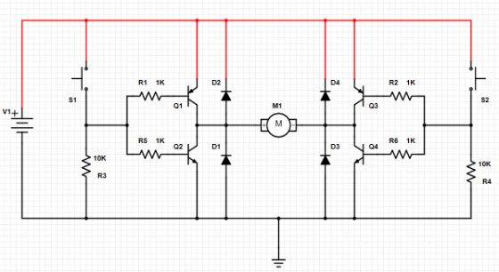
The H-bridge is a simple circuit consisting of four transistors, with two N-types and two P-types. The P-type transistors are situated on the high side of the motor (which connect to the power rail) while the N-type transistors are situated on the low side of the motor (which connect to the ground rail). Each side of the motor is connected to a simple push-pull amplifier, with each amplifier connected to a switch. Depending on the state of the switches, the motor will behave differently:

The switch determines if the PNP or NPN is turned on. If the switch is pushed, then the base-emitter region of the PNP will be 0V and turns that transistor off while the base-emitter region of the NPN is positive and turns that transistor on.
If the switch is not pressed, then the base-emitter region of the PNP will be negative and turns that transistor on while the base-emitter region of the NPN will be 0V and turns that transistor off. With the two push-pull amplifiers on each side of the motor, the direction of the current flowing through the motor can be controlled.
If S1 is pressed, Q1 turns off and Q2 turns on, and if at the same time, S2 is not pressed, then Q3 turns on and Q4 turns off. This causes current to flow through Q3, through the motor, and then through Q2 which causes the motor to turn counter-clockwise.
If S1 is left un-pressed, then Q1 turns on and Q2 turns off, and if at the same time, S2 is pressed, then Q3 turns off and Q4 turns on. This causes current to flow through Q1, through the motor, and then through Q4 which causes the motor to turn clockwise.
Motors are large inductors, so they can produce some large negative voltages when they slow down or stall. It’s imperative, then, to use clamping diodes. Our circuit has four clamping diodes (D1, D2, D3, and D4), which all protect the transistor they are next to.
This example takes advantage of low currents, a voltage supply of only 1.5V, and the use of a solar motor. Since the current draw in this example is quite low, we can use low-powered transistors (such as the 2N3904) for the sake of demonstration. However, when using larger motors that require amps of current, it is imperative that to use transistors capable of handling the motor current.
But even then, using discrete transistors can be difficult to route, which is why many designs use specialized H-bridge ICs that contain all the needed circuitry, as well as appropriate thermal contacts for removing dissipated heat during operation. (Remember, motors are power-hungry devices that can cook even the largest transistors!) When we go on to build motor drives for robots in the future, we will look at motor ICs and how much more convenient they are!
To learn more about transistors and see this article about transistor basics.
To see other projects involving transistors see these articles: Night Light Circuit using a PNP Transistor
Field Effect Transistors (FET) , How to Drive a Stepper Motor
To search motors on DigiKey’s site, for AC/DC go here, for Stepper Motors go here.