Resistor Power Rating, Derating, and Temperature Coefficient
2015-12-15 | By Amos Ndegw
Resistors are designed to limit the flow of electric current in a circuit. As the current flows, the resistor absorbs part of the electrical energy and dissipates it as heat that increases the temperature of the resistor to a value higher than the ambient temperature.
The power rating of a resistor indicates the maximum amount of energy it can dissipate without failing or degrading. The rating, based on the physical size of the resistor, the construction material, and ambient temperature, is limited by the maximum hot-spot temperature.
The amount of heat generated that remains within a resistor largely depends on how the dissipated heat is carried away from the resistor and is therefore a function of the ambient temperature, air flow, or heat transfer conditions.
Resistance changes with temperature
The resistance of most conductor materials varies with temperature changes. The temperature coefficient of resistance (TCR) is a constant that represents the resistance change per degree Celsius of temperature change over a specific temperature range; it’s expressed as ppm/°C (parts per million per degree centigrade).
The positive temperature coefficient (PTC) materials such as metals have resistances that increase as the temperature increases. Semiconductor materials such as silicon, germanium, and carbon have negative temperature coefficients (NTC); their resistances decrease as the temperature increases.
Some metal alloys have neutral or almost zero temperature coefficients and their resistances do not change with temperature changes; these are ideal for making precision resistors.
Because resistance is usually specified at the ambient temperature of 20°C, any other resistance at another temperature is determined by:
R= Rref[1+α(T -Tref)]
Where
R = resistance at temperature, T
Rref = resistance at reference temperature Tref
α = temperature coefficient of resistance
T = material temperature in °C
Tref = reference temperature at which the temperature coefficient is specified
The increase or decrease of resistance due to temperature rise may introduce errors and reliability issues in addition to increasing the heat dissipation and self-heating of the PTC resistors.
Derating resistors
Derating is a design technique where components are operated at less than their rated maximum parameters. This reduces the degradation rate and increases the component’s life expectancy and reliability. This also allows flexibility for the designer, allowing the component to work in harsher environments than their test conditions but at less than their rated maximum. When operating conditions such as case temperature, ambient temperature, cooling mechanism, grouping, and power dissipation of neighboring components deviate from the standard, they reduce the resistor’s power dissipation, performance, and reliability.
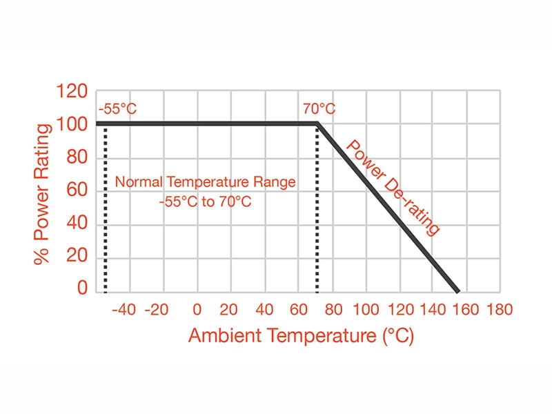
Most manufacturers specify the power rating at 70°C and free airflow conditions. At temperatures above 70°C, the resistor is derated using the electrical stress ratio.
Stress Ratio = Operating Power / Rated power
The recommended value is 80% for fixed resistors and 75% for variable resistors. The values at different temperatures are provided by the derating curves.
The process follows standards and guidelines from the derating curves provided by the manufacturer, the military, or other regulatory agencies. The curves provide data for the main operating and design conditions likely to be encountered.

Figure 1: Temperature derating curve
Image Source: learnabout-electronics
The power rating—as well as the derating curve—specifies the temperature up to which the maximum power rating is applicable (70°C). Also specified is the temperature at which the power rating must be derated to zero dissipation (150°C), which is also the maximum storage temperature of the resistor.
The derating increases the safety margin between design limits and the applied stress, and incorporates sufficient design margins to accommodate variations in power supply levels, operating temperature, and other environmental stresses. In addition to the temperature derating curve as shown in figure 1, other curves are available for derating based on enclosure, grouping, and altitude.
The resistor should be operated inside the derating curve envelope to guarantee performance specified by the manufacturer. If outside the curve, the design should incorporate additional measures such as heat sinking, forced cooling, connecting resistors in parallel, or larger physical size resistors.
Have questions or comments? Continue the conversation on TechForum, DigiKey's online community and technical resource.


