Practical Considerations in Reading a Diode Datasheet
2015-08-25 | By Maker.io Staff
Datasheets for diodes provide ratings for current, voltage, and other parameters that engineers consider when designing circuits. These datasheet ratings are based on assumptions that, if not considered, may lead to less than optimal results. This paper discusses key datasheet parameters such as operating junction temperature, voltage rating, forward voltage drop, and current ratings, and offers practical advice for using diodes well.
Operating junction temperature
Electronic components have maximum operating temperatures. Diodes are no different. A typical diode will have a rating for maximum junction temperature. If that rating is exceeded, the diode will be damaged, maybe irreversibly, and may catch fire. Do not confuse the package temperature with the junction temperature, which depends on factors such as forward voltage drop, current, ambient temperature, and heatsinking. (The junction is inside the package.)
Voltage rating
Voltage rating is called reverse bias voltage rating or DC blocking voltage. If the voltage rating is exceeded, the diode will fail and be damaged permanently. Use a diode that has a higher voltage rating than is expected in order to give yourself a margin of protection, and provide for room with transients. The amount of headroom needed depends on the application and depends on parameters such as switching speed and how much inductance is nearby. I like 20% headroom as a general rule.
Forward voltage drop
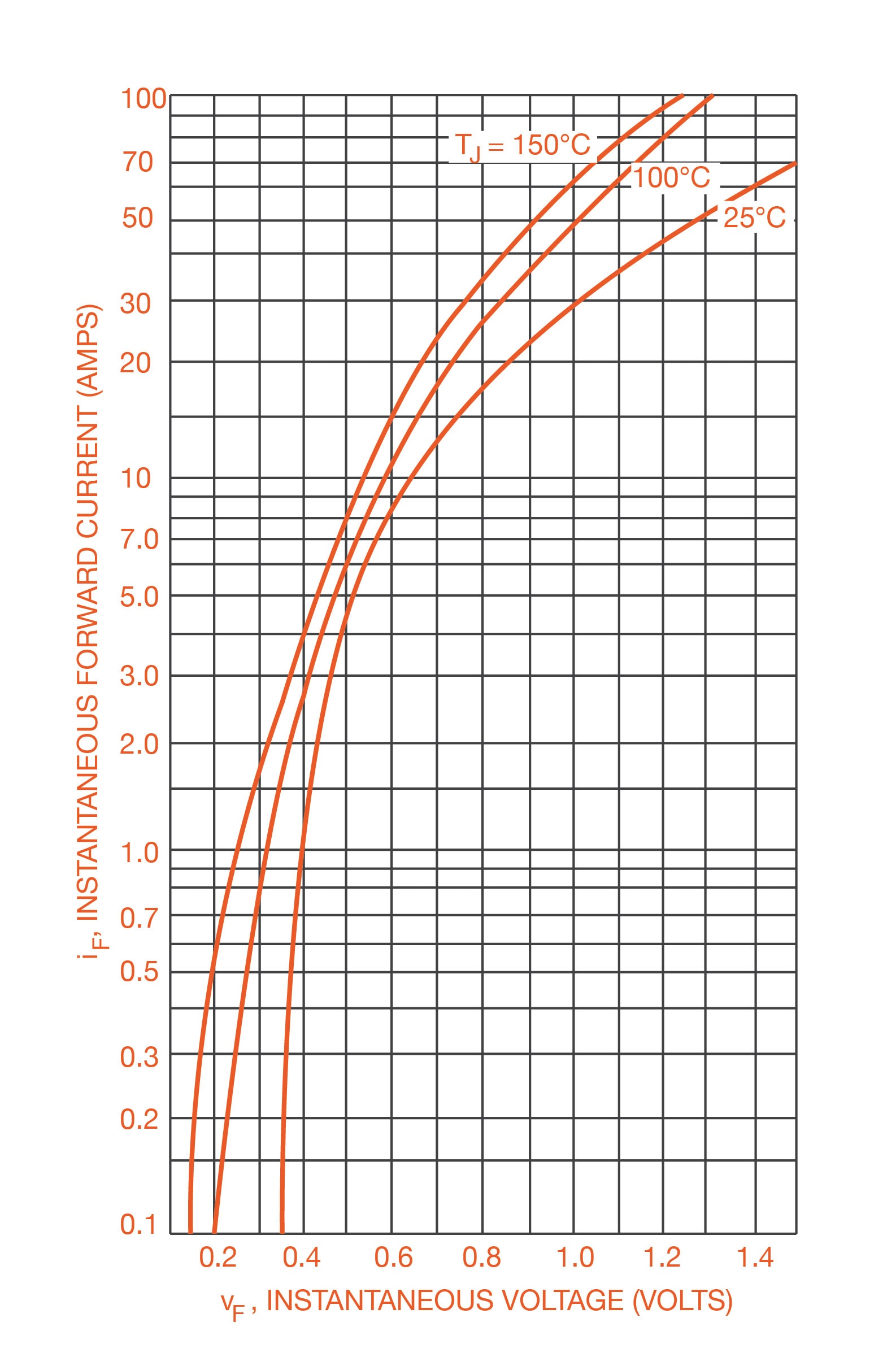
The forward voltage drop is the voltage that appears across the anode and cathode when a current flows through the diode. The forward drop may be specified as a single number at the top of the datasheet, but actually varies with current, as demonstrated in figure 1.

Figure 1: Forward voltage drop
Current rating
Datasheet current ratings are based on assumptions about how the diode is heatsinked and ambient temperature. Make sure that your application meets these assumptions.
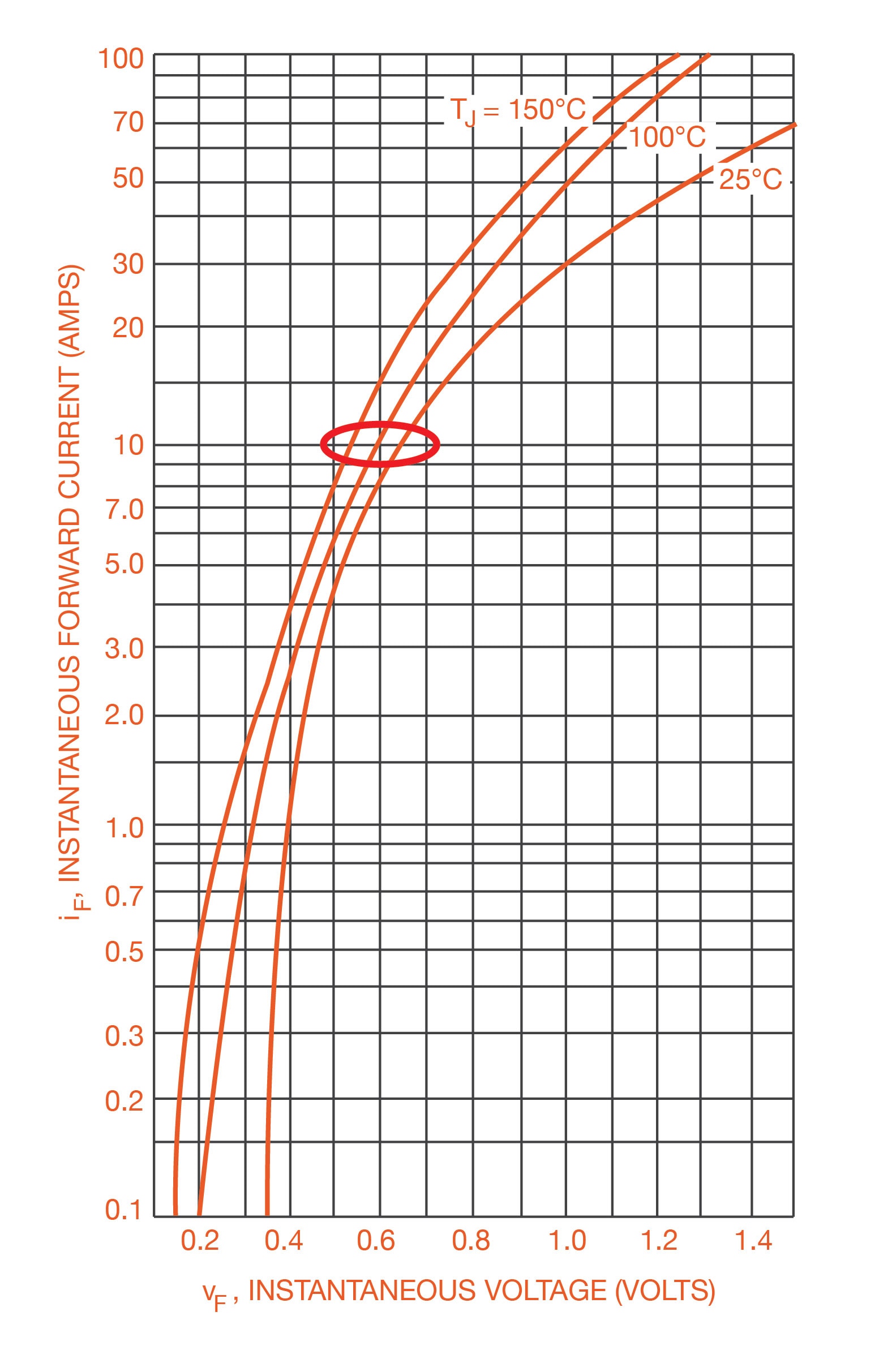
Example: The MBR1045G Schottky diode has a datasheet current rating of 10 A. From the datasheet V-I plot, we see that the forward voltage will be between 0.55 V and 0.65 V when the diode current is 10 A.

Figure 2: Forward voltage drop
When the diode is conducting 10 A, the power will be P=V*I=5.5W to 6.5W.
The diode has a junction-to-ambient thermal resistance θJA of 60 C/W, meaning that for every watt of power in the diode, there will be a 50 C temperature rise. The junction temperature can be calculated using this formula : TJ=TAMB+I*VF^ *θJA,
Where:
I is the current, measured in A.
VF is the forward voltage drop, measured in V.
TAMB is the ambient temperature, measured in C.
θJA is the junction-to-ambient thermal resistance, measured in C/W. It is the sum of junction-to-case thermal resistance, case-to-surface thermal resistance, and surface-to-ambient thermal resistance, as shown by this formula: θJA=θJC+θCS+θSA
If we try to pass 10 A through the diode without a heatsink, the temperature rise will be between 330 C and 390 C. The actual junction temperature will be between 355 C and 415 C in an ambient of 25 C. The diode is only rated for operation at 175 C maximum junction temperature.
We want to keep the operating junction temperature as low as practically possible. Thermal resistance between the junction and ambient temperature is calculated using this formula. We can reduce the overall thermal resistance by using a heatsink.
The DPAK package has a junction-to-case thermal resistance of 2 C/W. A heatsink like the 530002b00000g, which has a surface-to-ambient thermal resistance of 10.4 C/W. Attaching the heatsink to the diode and using a little thermal grease to help reduce the case-to-surface thermal resistance, we get a thermal resistance between the junction and ambient of 12.4 C/W. In this case, we can pass the same 10 A with a temperature rise of approximately 49.6 C to 86.8 C. If the ambient temperature is 25 C, then the junction temperature will between 74.6 C and 111.8C, which is well below the 175 C.
The temperature rise can be further reduced by selecting a diode with a lower forward voltage VF and/or a lower junction-to-case thermal resistance θJC. It is good practice to use Schottky diodes instead of pn-junction diodes for high current applications where possible. Schottky diodes have lower VF than pn-junction diodes, so they will generate less heat, and run cooler. Schottky diodes are also superior for switching applications like freewheeling diodes in buck converters and motor drivers because they have much lower capacitance and can switch faster.
Conclusion
Datasheets for diodes provide device parameters that measure device performance. Understanding the considerations behind the ratings helps engineers make wise design decisions. We have discussed key parameters such as operating junction temperature, voltage rating, forward voltage drop, current ratings, and practical considerations useful for diode selection.

Have questions or comments? Continue the conversation on TechForum, DigiKey's online community and technical resource.
Visit TechForum


 中国
中国