


Lithium Ion Cell Protection
2015-12-14 | By Dave Knight
Lithium batteries have the advantage of high energy density. However, they require careful handling. This article discusses important safety and protection considerations when using a lithium battery, introduces some common battery protection ICs, and briefly outlines selection of important components in battery protection circuits.
Overcharge
Lithium batteries can be safely charged to 4.1 V or 4.2 V/cell, but no higher. Overcharging causes damage to the battery and creates a safety hazard, including fire danger. A battery protection circuit should be used to prevent this.
Over-discharge
Lithium batteries are completely empty when discharged to 2.5 V/cell. Discharging a lithium cell this low is stressful to the cell and reduces cell lifetime. A good battery protection circuit will also provide over-discharge protection.
Discharge too quickly
Lithium batteries should not be discharged too quickly. Lithium batteries have maximum discharge current ratings. A battery protection circuit will take the battery out of the circuit if the load current is too high.
How battery protection circuits work
Battery protection ICs typically use MOSFETs to switch lithium cells in and out of circuit. Lithium cells of the same age and part number can be paralleled and share one protection circuit.
Figure 1 is a typical application schematic for a Texas Instruments BQ29700. It shows a BQ29700 connected to two MOSFETs, labeled CHG and DSG, and the cell terminals. The CHG MOSFET will turn off if the voltage at the cell terminals is too high. The cell can still discharge through CHG’s body diode and through DSG, so long as DSG is turned on. If the cell is discharging too quickly, or the cell voltage is going too low, then DSG will turn off, preventing further discharge. The cell can still be charged through DSG’s body diode, and the CHG MOSFET, so long as CHG is turned on.
Battery protection ICs are available from many manufacturers. Figure 2 shows the application schematics for Seiko’s S-8200A Series lithium cell protection ICs. Seiko has several lithium cell protection IC product families. Figure 3 shows the application schematic for another lithium cell protection IC, the DW01-P. Notice that the application schematics for all three circuits are very similar.
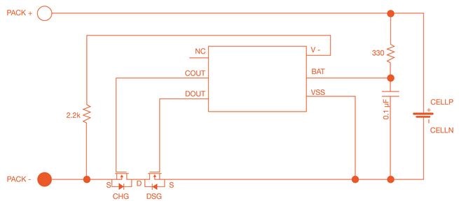
Figure 1: Typical application schematic for Texas Instruments BQ29700D
Image Source: Texas Instruments
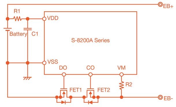
Figure 2: Typical application schematic for Seiko Instruments S-8200A Series battery protection ICs
Image Source: SII
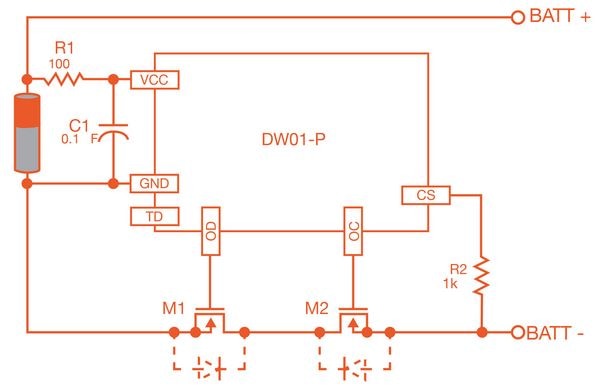
Figure 3: Typical application schematic for DW01-P
Considerations in choosing battery protection ICs
Two important parameters in battery ICs are overvoltage threshold and undervoltage threshold. These numbers are the voltage levels at their limit; the IC will cut the cell out of circuit if the cell is being overcharged or over-discharged. These values are typically designed into battery protection ICs. These ICs come in a variety of threshold mixes, giving engineers a wide variety of choices.
Overvoltage protection threshold
Lithium batteries have more charge during each charge cycle if they are charged to 4.2 V. However, they have longer life if they are charged to 4.1V. The design engineer has to strike a balance between charge per cell and lifetime when choosing an overcharge voltage threshold.
Over-discharge protection threshold
The over-discharge protection threshold also has an impact on capacity/charge and cell life. A battery will have more capacity per charge if it is discharged all the way. However, this is stressful on the battery and will reduce the lifetime of the battery.
MOSFET selection
A key element of a battery protection circuit are the MOSFETs used to switch the cell in and out of the circuit. MOSFETs with low RDS(ON) should be used to achieve high efficiency. Use MOSFETs with low Vt because the battery protection IC may only have 2–3 V to drive the gate.
Conclusions
In this blog, we have covered basic considerations in lithium cell protection and in choosing a battery protection IC, looked at some common battery protection ICs from multiple vendors, and briefly discussed MOSFET selection.
Have questions or comments? Continue the conversation on TechForum, DigiKey's online community and technical resource.

