Creating a Simple Windows IoT Application
2016-05-02 | By Maker.io Staff
Breadboards Wire Jumper Wires Resistors Raspberry Pi
If you have followed my previous guides, by now you should be up and running with Windows 10 IoT on the Raspberry Pi and be able to upload an application to your device. Now I’m going to show you a few simple steps in creating your own interactive application with the GPIO pins on the Raspberry Pi board.
Kick-starting your development in Windows 10 IoT can be daunting at first, especially if you are unfamiliar to programming in C# and unfamiliar with using the Visual Studio programming environment. If you have not yet setup your Windows 10 IoT device, then use the following guide to help:
- - How to Install Windows 10 IoT Apps on the Raspberry Pi – This will help you install Visual Studio and load an application to blink an LED.
This following tutorial will show you how to setup a basic Windows 10 IoT application in which we will create two buttons to control two different LEDs. One LED will be controlled to simply switch on or off and the other LED will blink intermittently when you press the button in the application.
What you will need
- - A Raspberry Pi running Windows 10 IoT Core
- - Visual Studio 2015 (Community Edition - Free)
- - Breadboard - 700-00078-ND
- - Male to Female jumper wires - 1471-1231-ND
- - 2x LEDs (Any color) - 67-1066-ND (Red) or 67-1060-ND (Green)
- - 2x 270ohm Resistors - 270QBK-ND
Setting up Visual Studio 2015
You will need to create a new project in Visual Studio and import the Windows 10 IoT references. To do this click File > New > Project.
Choose a Windows/Universal Blank App and name the project.

Figure 1: Start a new Project in Visual Studio
Once the project is opened in Visual Studio navigate to the Solution Explorer on the right hand side and right click References and choose Add Reference.

Figure 2: Adding new reference
Add-in the Windows IoT 10 reference under Universal Windows > Extensions, click ok.
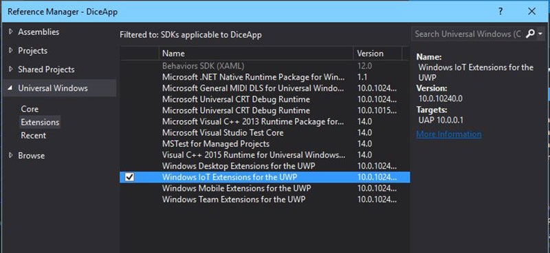
Figure 3: Add Windows IoT 10 reference
The reference will now be added to the reference list.
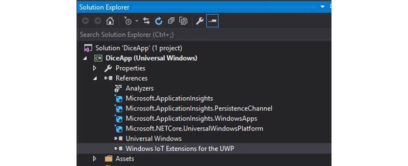
Figure 4: Windows IoT 10 reference added
Before you write code against an external component or connected service, your project must first contain a reference to it. A reference is essentially an entry in a project file that contains the information that Visual Studio needs to locate the component or the service.' So for the Raspberry Pi project you'll need to add the reference so you can use the GPIO pin components and control them.
Creating the IoT Interface
Before we get stuck looking at the code, let’s create our interface so you can switch the LEDs on and off. To do this go to the Solution Explorer window and right click the MainPage.xaml and click View Designer.
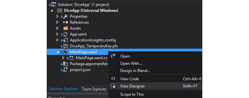
Figure 5: Opening View Designer
This will open up the Designer view in the main body of Visual Studio. Before we start tinkering with the Designer view you need to select the desired window size in which you will view the application. I’m using the Raspberry Pi official 7” Touchscreen therefore I will select the 6” Phone window to work with- you can select your target window here.
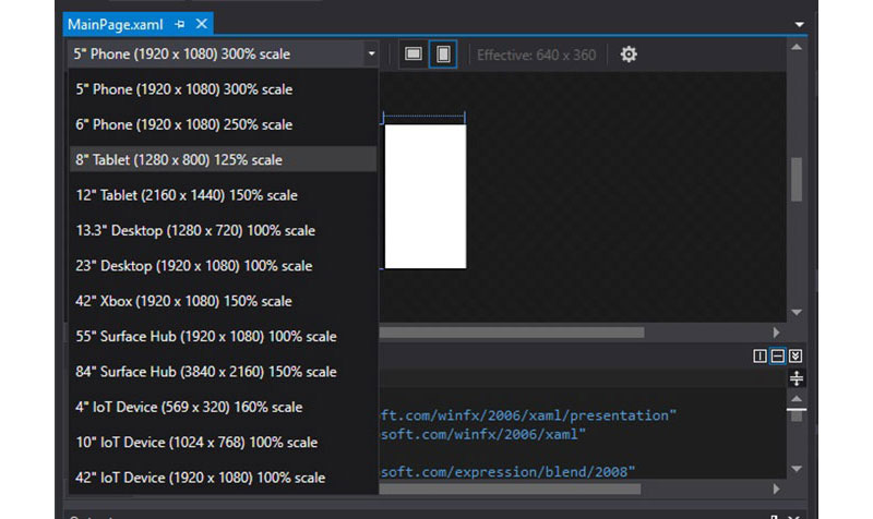
Figure 6: Selecting your device
You can now start adding elements to the design. For the IoT interface in our application you will need to add two buttons to the design. You can do this by opening the Toolbox window in Visual Studio; click View > Toolbox from the menu. From within the Toolbox menu drag two buttons to the design Window.
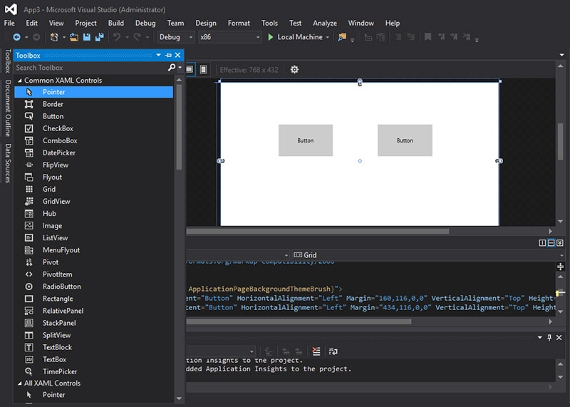
Figure 7: Drag two buttons to the Design window
Now that you have the two buttons in your interface, you need to define how to interact with them and what they will do. For both buttons they need to be define as we click them, to do this we create an event handler for the button.
First highlight one of the buttons and in the properties window give it a name, I have called my first button redButton as I will use this to turn on a red LED. Next click on the event handler icon.
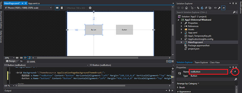
Figure 8: Click the event handler icon
Enter here some information in the Click section of the event handler. I have named it redButton_click.
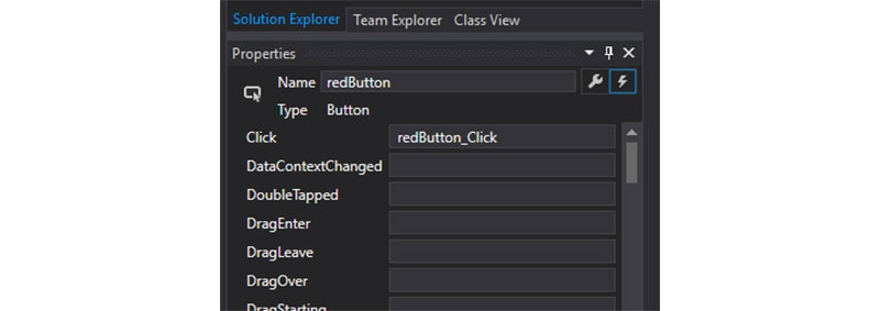
Figure 9: Enter a name for the Click event handler
This will create a block of code within the MainPage.xaml.cs. This block of code will determine what happens when you click that particular button.
- private void redButton_click(object sender, RoutedEventArgs e)
- {
- }
Now do the same with the other button, make sure you select it first in the designer view window and then make the changes. I have named this particular button Blink as that is exactly what it will be used for, to blink an LED.
Now let’s label the buttons so we know which one does what in the application. For the first button click the settings icon in the button’s properties and in the Content field enter the name of what you want to call it. I have labelled the first button on/off and the second button Blink. You will see the updates in the design view in the main window.
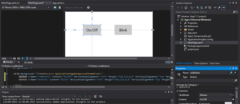
Figure 10: Label the buttons
That’s pretty much the basics for adding elements to the user interface in our application. Next let’s look at building the code to turn some LEDs on and off.
Building the Code
So far we’ve been setting up the interface using the design view and this has been making some changes to the MainPage.xaml. The file associated with this is the .cs file – MainPage.xaml.cs, this is where our main code is. In our code we need to achieve the following outcomes:
- - Initialize the GPIO pins, turn them off and set them as an output
- - Check if the GPIO pins are available
- - Clean-up the GPIO pins upon exit
- - Turn on or off the red LED when the button is pressed
- - Flash the Green LED when the second button is pressed
Start by clearing any unnecessary code that we don’t need, by default the application adds most perquisites it thinks it may need. At the top of the code click into this using the Directive section. You should see a lightbulb appear on the left-hand side. Click the drop-down button next to it and choose Remove Unnecessary Listings. You should see the code in the main application highlighted for removal, go-ahead and do this.
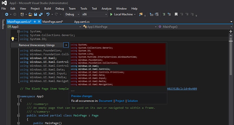
Figure 11: Remove Unnecessary Listings
To be able to use the GPIO pins we need to add in the Windows.Devices.Gpio namespace with the command 'using Windows.Devices.Gpio;
Figure 12: Add GPIO devices to the application
In the 'public sealed partial class MainPage : Page' section of code we are going to declare all the variables we need for the project. We need to set which GPIO pins to use and give them a name.
You can refer to a GPIO pin diagram to determine which pins to use and the GPIO value of the pins. For this application I have used GPIO pins 5 and 18 for the LEDs.
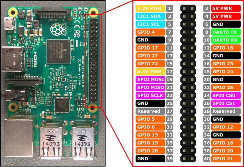
Figure 13: Raspberry Pi GPIO Pinout diagram
Add the following code:
- private int red_state = 1;
- private bool green_state = false;
- private const int RED = 5;
- private const int GREEN = 18;
- private GpioPin redPin;
- private GpioPin greenPin;
Now that we have declared our variables we need to initialize the GPIO pins. By default GPIO pins are set to input so we need to set their mode to ouput.
In the section public MainPage() enter InitGPIO();.

Figure 14: Initialize GPIO pins
Next create a private void called InitGPIO(), add the following code:
- private void InitGPIO()
- {
- var gpio = GpioController.GetDefault();
- redPin = gpio.OpenPin(RED);
- greenPin = gpio.OpenPin(GREEN);
- redPin.Write(GpioPinValue.Low);
- greenPin.Write(GpioPinValue.Low);
- redPin.SetDriveMode(GpioPinDriveMode.Output);
- greenPin.SetDriveMode(GpioPinDriveMode.Output);
- }
Now before we get to the main part of the code where we actually make something happen, one important step is to tell the application what happens to the pins when you close it down or stop it. We need to make sure the pins are release after it has closed for other applications otherwise this will cause issues and a full re-boot would be required. We can use the Dispose method to accomplish this.
In the MainPage() section add the following code Unloaded += MainPage_Unloaded; the code in this section should now look like the following.

Figure 15: Main Page Unload
Create a private void called MainPage_Unloaded and add the following code:
- private void MainPage_Unloaded(object sender, object args)
- {
- redPin.Dispose();
- greenPin.Dispose();
- }
Now that we have sorted out what happens when the application exits we can now focus our attention on what happens when we click the buttons. If you remember when we created the button in the design view it also created some code in the MainPage.xaml, this is where we add the code to determine what happens.
Add the following code to the first button:
- private void redButton_click(object sender, RoutedEventArgs e)
- {
- if (red_state == 0)
- {
- redPin.Write(GpioPinValue.Low);
- red_state = 1;
- }
- else if (red_state ==1)
- {
- redPin.Write(GpioPinValue.High);
- red_state = 0;
- }
- }
We set a variable as red_state to determine the state of the button. When we know the state of the button then we can decide whether to turn the LED on or off. We use simple IF statement for the conditioning of the state and then we write the LED value to either HIGH or LOW, also we must ensure that the state of the button is then changed for next time the button is pressed.
Add the following code for the second button that blinks the LED on and off:
- private async void blinkButton_click(object sender, RoutedEventArgs e)
- {
- green_state = !green_state;
- while (green_state == true)
- {
- greenPin.Write(GpioPinValue.High);
- await Task.Delay(500);
- greenPin.Write(GpioPinValue.Low);;
- await Task.Delay(500);
- }
- }
This code is a little bit different in terms of reading the state of the switch, I’d thought I would give you two examples using both integer values and also Boolean. In this example we have used Boolean logic to determine the state of the switch, initially when the button is clicked it reverses the value of state, which then initializes the while statement. The while statement is a simple loop the continuously runs until the condition is no longer met i.e. the button is pressed again and the state then becomes false.
In order to use the delay function in this statement there are a few key things that need to be in place before hand such as at the beginning of the code we must insert using System.Threading.Tasks; which gives access to the task delay. Also within the button void it must become asynchronous when you use the await function, what this does is create a background thread for the task rather than halting the entire program.
Building the Circuit
Now that we have everything setup in our code we can now focus our attention on building the circuit for the LEDs. Check out the Fritzing diagram below to learn how to connect the LEDs to the Raspberry Pi’s GPIO pins.
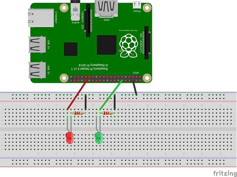
Figure 16: Connecting the LEDs to the GPIO pins
Wire up the LEDs as shown in the diagram, the black wires are connected to the ground on the Raspberry Pi and the red wire is hooked up to the red LED and the green wire to the green LED to avoid any confusion, the resistors are connected in series with the LED. If in doubt you can always refer to the Raspberry Pi GPIO diagram for the pin number reference.
Upload and Run
With the circuit now built we need to run the code within Visual Studio. This will upload to the Pi and report back if there are any errors in the code. So power up the Windows 10 IoT O/S and take a note of the IP address displayed on the screen.
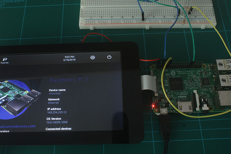
Figure 17: Boot up the Raspberry Pi
Now in Visual Studio choose Debug & ARM from the drop down menus. Then click the Device drop down and choose Remote Machine.

Figure 18: Select Remote Machine
In the Remote Machine window enter the IP address of your Raspberry Pi and choose 'None' for authentication. Click Select.
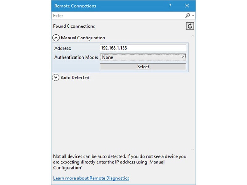
Figure 19: Insert IP address for remote connection
Back on the main screen click the Remote Machine button to upload the code to the Pi.

Figure 20: Click the green arrow to upload to the Pi
Visual Studio will output information on the upload any failures that will need to be address.
When successfully uploaded you will see the application running on the Raspberry Pi and you will see the interface that we creating with the two buttons. Click the buttons and you should see the LEDs light up.

Have questions or comments? Continue the conversation on TechForum, DigiKey's online community and technical resource.
Visit TechForum


 中国
中国