Constant Power Load using PWM and ADC | Maker.io
2016-02-10 | By Dave Knight
This article discusses the basic ideas of pulse-width modulation (PWM) and analog-to-digital conversion (ADC), and describes a circuit and firmware using these tools to create a constant power load with closed-loop feedback.
Introduction to PWM
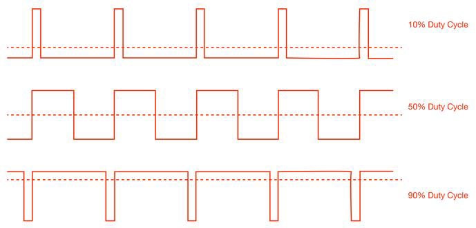
Pulse-width modulation (PWM) is a method of producing a square wave with a variable duty cycle. Duty cycle, abbreviated D, is the fraction of the time that the wave is high. The average value of the signal is (D/T)*Max.

Figure 1: Duty cycles
Image Source: http://www.bristolwatch.com/PIC18F2550/PIC18F2550_pwm.htm
ADC
An analog-to-digital converter (ADC) converts an analog voltage to a digital number for use in a microcontroller. A 10-bit resolution is typical, meaning that an ADC reading will be in the range of 0–1023. The answer is indicative of the fraction of the voltage over whatever reference is used. If a 5 V VDD is used as a reference and the analog input is 3 V, then the ADC result would be 1023*⅗, which is about 614. ADC answers are always integers.
Constant power load
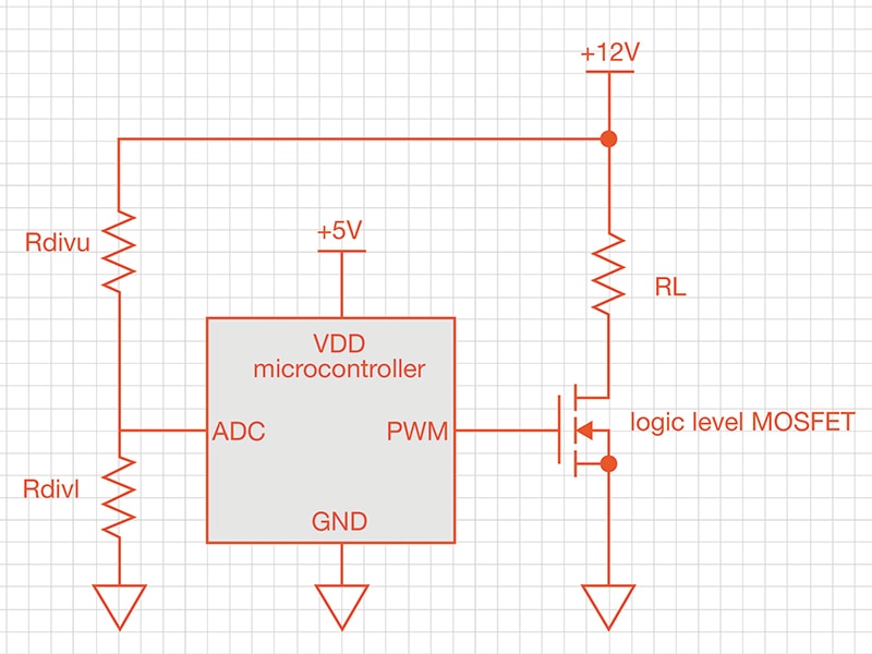
PWM has a wide range of applications from audio amplifiers, to motor controllers, to power converters. It can also be used to make a constant power load using the circuit in figure 2, a microcontroller driving a logic level MOSFET through its PWM pin. The MOSFET pulls one side of a load resistor to ground, while the other side is connected to a 12 V source. A resistor divider from the 12 V power source feeds the ADC pin of the microcontroller. This allows the microcontroller to measure the power supply voltage, and form a closed-loop control of the power dissipated in the load resistor.

Figure 2:Microcontroller driving a logic level MOSFET
PWM frequency
Many microcontrollers contain PWM peripherals and often use a timer as a base for the period. The duty cycle of the PWM can be changed by writing to registers. Timers and PWMs have finite frequency and duty cycle bits in the register. Typically faster frequencies have less granular control over duty cycle. Also, remember that driving a MOSFET does use power; a microcontroller’s pin isn’t really designed to source enough current for really high-speed MOSFET driving. Consider the current rating of the microcontroller pin when choosing frequency. I choose to drive mine around 30 kHz, so nobody would hear it (audio frequency is up to 20 kHz). Switch faster than 20 kHz if you don’t want anyone to hear the switching action.
MOSFET selection
A logic level MOSFET with low RDS (ON) is used. Logic level is important because we’re running off a 5 V microcontroller, and we want to be sure that the MOSFET’s Vt is low enough to be turned on all the way by the microcontroller. Choose something that is appropriately sized for the level of current the resistor will be sinking (I=V/R). Choose something with relatively low gate capacitance that the microcontroller won’t struggle to drive.
Load resistor
Ohm’s Law: P=V*V/R
Ohm’s Law with PWM: P=V*V/R*D
The average power is P=V*V/R*D. The instantaneous power is P=V*V/R. Choose a resistance that won’t burn up or exceed the power supply’s current rating, and choose a resistor size (package) based on how much power will be dissipated. The power rating may depend on layout considerations or heatsinking. Consult the resistor datasheet. If you are concerned about the resistor getting hot, or if this is a prototype, you can heatsink the resistor.
Resistor divider
Choose resistors that will dissipate little heat, and provide low enough source impedance to the ADC pin. Typically, 10k is as high a resistance as should be used to drive an ADC pin.
Firmware
The microcontroller should periodically do an ADC reading on the power supply voltage. This is used to adjust the duty cycle of the PWM to get the desired power draw: P=V*V/R*D, where D is based on the power supply voltage.
Have questions or comments? Continue the conversation on TechForum, DigiKey's online community and technical resource.


