制造商零件编号 A000066
ARDUINO UNO R3 ATMEGA328P BOARD
Arduino
License: See Original Project Arduino
Courtesy of All About Circuits
A TV remote is one fun way to control an Arduino. In this project, you’ll learn how you can use any button on a standard infrared TV remote control to activate functions on an Arduino.
Required Materials
Download and Install the IRRemote Library
You’ll need to download a multi-protocol infrared remote library, the one used for this project was developed by Ken Shirriff. This infrared remote library allows the Arduino to decode and transmit the infrared signals that most commercial remote control systems use. Ken Shirriff made a tutorial on how to use the library that I highly recommend reading.
To download a copy of the IRRemote Library, go to his GitHub page and click the “Download ZIP” button on the right side of the page.
Next, you’ll need to extract all the files, then, move the "IRRemote" folder that has been extracted to your Arduino libraries directory. The most recent versions of the Arduino software have another folder called “RobotIRremote” that’s already in the library directory. The “RobotIRremote” folder has a subfolder in it that is also named “IRRemote.” If there are two of these folders are in the library, the Arduino will generate an error because it won’t know which one to reference. Deleting the “RobotIRremote” folder is the easiest way to resolve this problem. If you don’t want to delete that folder, you can go into the subfolders and rename all the folders that cause conflicts.
Connecting the Infrared Receiver Module
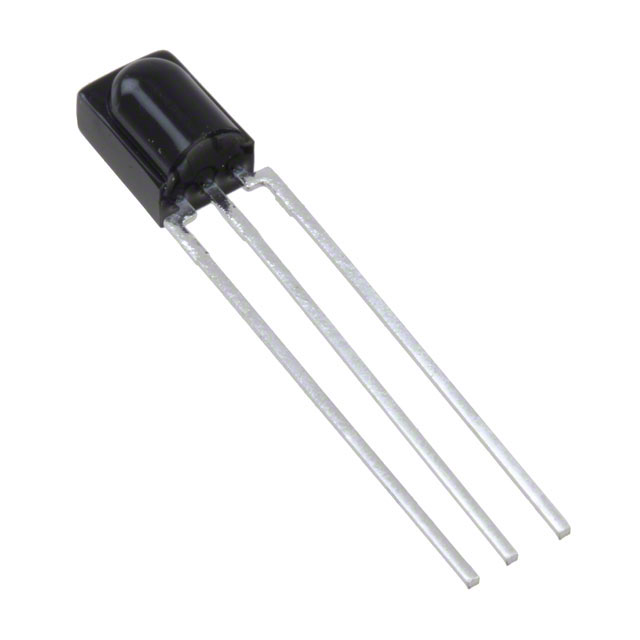
There are three pins on the infrared receiver module. As shown in the picture below, the right pin is connected to 5V. The center pin is connected to GND. The pin on the left is the output pin, it connects to one of the digital pins on the Arduino set to input mode. This pin configuration may can differ depending on your part’s manufacturer. Be sure to consult the manufacturer’s datasheet before hooking the infrared receiver module up. This in the only part needed for your Arduino to receive infrared signals. Once you’ve made these connections, you are ready to set up code.
The Arduino Code
Using this code allows the Arduino to constantly monitor the IR receiver module’s output. When a signal from a remote is detected, the IR receiver module decodes the signal and converts it into a numerical value. This value is stored in a variable that can be used to activate any functions that you’d like to add into the code. The serial Monitor tool allows you to see the number values generated by each button on your remote. Once you know the values, all you need to do is add them into the code and set up conditional statements that will perform the desired action whenever a specific button on the remote is pressed. When writing the code, keep in mind that many remotes will send the same code multiple times or send a series of codes every time you press a button.
#include <IRremote.h>   //include IR remote libraries

unsigned long CurrentValue = 0;   //stores current signal value
int RECV_PIN = 12;   //pin to receive the signal from the infrared module
IRrecv irrecv(RECV_PIN);
decode_results results;

void setup()
{
 Serial.begin(9600);
 irrecv.enableIRIn();   // Start the receiver
}

void loop()
{
if (irrecv.decode(&results))   // if a signal is detected
{
 CurrentValue = (results.value);  //stores last value received
 Serial.println(CurrentValue);   //displays stored code for reference
 irrecv.resume();   //resume detecting signals
}
}
Example Project
Here is an example to better illustrate how you can use this technique with your Arduino projects. I set up my Arduino to activate a relay whenever a certain signal is detected. This allows you use your remote to turn connected appliances on and of. I also added a “Program” button that allows me to change the set remote code while the system is operating.
First, the IR receiver module is connected to 5V, GND, and D12. Then, a 100 kohm resistor is connected between D10 and GND. The momentary switch is connected between D10 and 5V. A 100 ohm series resistor and an LED are connected to both D8 and D7. Lastly, a relay and a flyback diode are connected between D4 and ground. In general an Arduino’s output pins shouldn’t output more than 20 mA. So if your relay requires more than 20 mA, then it’s best to drive it with a power transistor.
The relay and diode were mounted on a separate circuit board, I enclosed them inside an insulated project enclosure. This allowed me to control AC appliances safely.
Next, you’ll need to upload the attached code.
When the button is pressed, the first LED will turn on, indicating that the system is now in “programming mode.” The next signal received by the system from a remote will be stored as the activation code. Pick a button on the remote that you want use and press it. When the code is received by the system, the second LED will turn on to indicate that the code is set. Now, the relay will turn on or off whenever you press that button on the remote.
It should be noted that the programmed functions will be reset if your Arduino is turned off. If you want the programmed function to be permanent, you will need to write the values into the code.
#include <IRremote.h>                    //include IR remote libraries

int RECV_PIN = 12;                       //pin to read the signal from the infrared module
IRrecv irrecv(RECV_PIN);
decode_results results;

//variables
unsigned long CurrentValue = 0;          //value received from the infrared module
unsigned long StoredCode = 0;            //saved code value
unsigned long previousSwitchTime = 0;    //last time marker that the output was toggled
unsigned long switchTimeDifference = 0;  //how long since the last output toggle
const int buttonPin = 10;                // the number of the pushbutton pin
const int programLedPin =  8;            // the number of the program LED pin
const int indicatorLEDPin =  7;          // the number of the output LED pin
const int relayPin = 4;

int buttonState = 0;                     //variable for reading the pushbutton status
int RecordState = 0;                     //is the reciever in record mode
int outputState = 0;                     //is the output on or off


void setup()
{
 Serial.begin(9600);
 irrecv.enableIRIn();                   //Start the receiver

 pinMode(buttonPin, INPUT);             //set digital pin modes
 pinMode(programLedPin, OUTPUT);
 pinMode(indicatorLEDPin, OUTPUT);
 pinMode(relayPin, OUTPUT);
}


void loop()
{
if (irrecv.decode(&results))                                    //if a signal is detected
{
 CurrentValue = (results.value);                                //save value
 Serial.println(CurrentValue);                                  //displays stored code for reference
 switchTimeDifference = millis() - previousSwitchTime;          //calculate time since last switch

 if(CurrentValue == StoredCode && switchTimeDifference > 1000)  // if the recieved value equals the programed value and the last state switch was more than 1 second ago, then toggle the output state
  {
   outputState = !outputState;
   previousSwitchTime = millis();
  }
 if (RecordState == 1)                                          // if the record mode is activated store the current value as the programed value
  {
   StoredCode = CurrentValue;
   RecordState = 0;
   digitalWrite(programLedPin, LOW);
   Serial.println(StoredCode);                                 //displays stored code for reference
  }

 irrecv.resume();                                              // Receive the next value
}
else                                                           //if no signal is detected, then the current value is 0
{
 CurrentValue = 0;
}

buttonState = digitalRead(buttonPin);                          // check if the record button is pressed.
if (buttonState == HIGH)                                       // if it is, the buttonState is HIGH:
 {
  while (buttonState == HIGH)                                  //wait for the button to be released
  {
   buttonState = digitalRead(buttonPin);
  }
  digitalWrite(programLedPin, HIGH);                          //turn on the LED to indicate that record mode is on
  RecordState = 1;
 }
if(outputState == 1)                                          //set the appropriate output state
{
 digitalWrite(indicatorLEDPin, HIGH);
 digitalWrite(relayPin, HIGH);
}
else
{
 digitalWrite(indicatorLEDPin, LOW);
 digitalWrite(relayPin, LOW);
}
}