Adding Wireless Charging the XRP: The Electronics
2024-08-20 | By Ramaditya Kotha
License: See Original Project
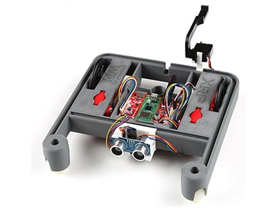
The XRP is a great robotics platform! However, I often find myself running out of AA batteries, and my XRP ends up on the shelf until I get more. To fix this problem, I created a wireless charging system with rechargeable Li-ion batteries and Adafruit boards so that my XRP is always charged and ready for my next project!
In this project, I’ll show you how to create the circuitry to wirelessly charge your XRP. In another post, Shruti G. will show you how to design and 3D print a receiver case, as well as a docking station to tidy up and hide away our circuitry!
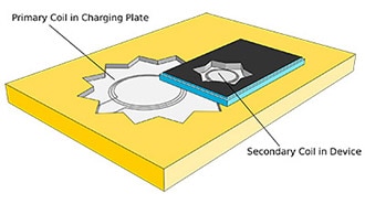
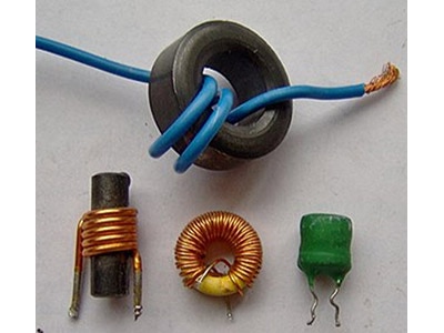
Before we get our hands dirty, let’s talk about and understand the high-level working principle of a wireless charger. Wireless chargers work on the principle of coupled inductors. Inductors are electrical components that store energy in a magnetic field. Two inductors that are aligned and close to each other can transfer energy.
Luckily Adafruit has a convenient module that takes care of the circuitry and theory of wireless charging for us! All we need to do is provide the transmission board with a 9-volt source, and we’ll get 5 volts at up to 1.2 amps on the other side!
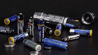
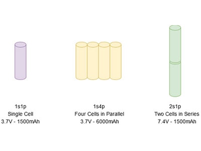
Because the XRP requires between 5 and 11 volts, we need to connect two of these 3.7-volt Li-ion cells in series (7.4 volts nominal).
To charge the batteries, we’ll be using a Li-Ion charger from Adafruit.
One issue with this setup is that most off-the-shelf Li-Ion battery chargers can only charge 1 cell at a time, and do not support charging two cells in series. Thankfully, we can use this clever wiring diagram from Adafruit to wire up our batteries so we can work around this limitation.
In order to create the circuit above, we’ll need a 3PDT switch. A 3PDT has three different switches inside it, with each switch having two possible positions. When we want the XRP to run, we can set the switch to “running mode,” which will put the batteries in series. When we want the XRP to charge, we can set the switch to “charging mode,” which will connect the batteries in parallel to the charging module. Lastly, we will power the Li-Ion charger with our wireless charging module, leaving us with the following full circuit:
With the planning out of the way, we can now get to creating the circuitry! Following the wiring diagram, lay out the wires where they go! Take care not to mix up the battery wires.
Solder a female JST PH connector to the charging input wires. This is necessary because the Adafruit board has a male JST PH connector. We could solder the wires directly to the board, but I do not recommend this, as it will make testing and troubleshooting the circuitry much more difficult.
Then, solder two male JST connectors to where the batteries connect to the switch! This is much better than soldering the batteries directly to the switch, as it will allow us to swap out batteries if we ever want to.
Finally, solder a 2.1mm barrel jack connector to the output. This will allow us to plug our circuit directly into the XRP.
Now that our circuitry is mostly done, we should probe a few points to make sure the circuitry is good! First and foremost, use the continuity feature on your multimeter to ensure that all the connections are correct.
After, you should check that the voltage outputs are correct. When the switch is set to running, you should see close to 7.4V at the output (it’s normal to be slightly higher). When the switch is set to charging, you should see no voltage at the output, and you should see 3.7V across the female JST connector (the one that goes to the Adafruit board).
Now, let’s solder the receiver module to the Adafruit board’s DCIN port. I chose to extend the length of the wire going to the receiver coil during this step. If you choose to do the same, be sure to heat up the wire well before soldering it! Otherwise, you’ll have a tough time getting the solder to tin the wires well. If you would like to add rechargeable batteries to your XRP, you could exclude the wireless charging module and simply charge your batteries via the USB cable on the charging module.
You can now plug your 2.1mm power connector into the XRP. Use a power supply or a 9V battery on the transmitter coil to test the circuitry. A 9V battery won’t last long, so just use it to briefly test. I ended up using a power supply.
Now you can place the coils on top of each other and set your power supply to 9V! In the charging position, you should see the charging lights on your Adafruit charging module light up. In the running position, the LEDs on the XRP should light up!
Unless you want to lug around a benchtop power supply everywhere you go, I highly suggest swapping out the 9V power supply for a 9V wall adapter. To be safe, make sure it supports at least 10 Watts!
And voila! Your XRP can now wirelessly charge! You could take this project further by designing a custom PCB to tidy up the wiring. You could also experiment with using relays or even MOSFETs to have the XRP autonomously switch between charging and running modes.


