制造商零件编号 2884
FEATHERWING PROTO - PROTOTYPING
Adafruit Industries LLC
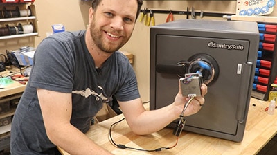
My brother-in-law, Levy, has a safe and doesn’t remember the combination. He called and asked me to see if it was possible to build a robot that could crack the safe combination, so of course, I told him I would give it a shot. If you haven’t read part 1 and part 2 of this build series, I suggest starting there.

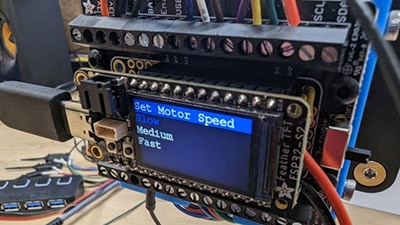
I’m getting close to being able to crack the combination of my brother-in-law’s safe, but a couple of things still need to be addressed. The stepper motor I used in parts 1 and 2 works great, but I noticed during my longer testing sessions it would sometimes get off track. Stepper motors are super precise, but they are still an open-loop system. That means there is no sensor to tell the motor when it has arrived at the target location. To close the loop, I need to add a position encoder to the shaft of the motor. So, I ordered this one, and it works great! Unfortunately, this one doesn’t have the motor driver built in like the last one, so I’m going to print an adapter to mount it to the new stepper motor. I’m also ditching the rotary encoder from part 2 because literally as I was building this project, Adafruit came out with an updated design of their ESP32 TFT display that has 3 buttons right next to the screen. It was fun to use the rotary encoder to cycle through the menu and make selections, but I think the 3 buttons on this new design can replace the large rotary encoder, which will save a lot of space.
I designed an enclosure to fit the new ESP32, and it uses small magnets that are embedded into the base to attach to the stepper motor. Another reason this new ESP32 design is so awesome is that it puts all the large and bulky components on one side of the board so I can mount the board and display flush up against the inside wall of my enclosure. The motor, the motor encoder, and the power plug all have dedicated wiring harnesses that connect to a featherwing protoboard inside the new enclosure. In the future, I would like to design a custom board with connectors for all these auxiliary components. I have to say I think this new enclosure looks way better than the previous method I used to mount the electronics.
With the stepper motor auto dialer part of this project working pretty well, I need to move on and figure out how I’m going to turn the handle on the safe after every combination. I thought about different options for motors. I ended up deciding to use a heavy-duty hobby servo motor with metal gears. I just needed to design another frame to hold the motor above the handle and print a servo coupler to hold onto the handle. I installed a limit switch that will tell the ESP32 when the handle has been opened all the way which means the auto-dialer has found the correct combination. The frame ended up being very similar to the frame I designed for the stepper motor part. No need to reinvent the wheel here! This servo frame uses large magnets to adhere to the safe door just like its older sibling.
I have a way to dial all the combinations of the safe, and I have a way to turn the handle after every new combination is set, so I’m ready to head over to my brother-in-law’s house and start integrating all the parts and finding out where I went wrong! Luckily most things worked just like I had imagined. It really helped to have built that mock-up safe door in part 2 of this series. I was able to work out a lot of bugs without having to be at my brother-in-law’s house. The only thing I hadn’t tested that failed was the 3D printed coupler that connects the servo motor to the handle of the safe. With a single revision, I printed a new part overnight and was back in business!
I’ve had an overwhelming amount of interest in this project. I think because of how relatable it is to screw something up (my brother-in-law forgot the combination to his own safe) and then try to rectify the problem with some good ol’ fashioned engineering. Instead of cracking the safe by myself, I decided that it would be way more fun to live stream the event. I didn’t complete any practice runs ahead of time to make sure I could crack the safe. I wanted to show everyone in real time my first attempt to open the safe. The stakes were high. Everyone who watched the live stream was either going to see my safe cracking robot (that took months to build) open the safe in a triumphant finale, or they would be there to comfort me when it failed miserably! My first attempt on the live stream wasn’t a total failure, but I didn’t crack open the safe either. I had problems with the handle not returning back to the fully retracted position before the stepper motor moved to the next position. This caused the sequence to get off. The viewers had lots of helpful suggestions. I found an exercise band nearby and used that to help the handle return back to the retracted position. It worked with mixed results, and this trial-and-error process lovingly became known to the viewers as the #handleScandal! There were several lessons learned, so off I went to fix more bugs.
About a week after the live stream event, I went back to Levy’s house to work on the safe. Unfortunately, I forgot my 12V power supply, so I started looking around his house for something similar. I found something that should have worked according to the label. But when I plugged it in, I heard a pop noise followed by the smell of magic smoke. It was immediately clear that I had destroyed the microcontroller with TFT display because it wouldn’t turn on after that. Later, I discovered that I had also destroyed the motor driver attached to the stepper motor. After this string of bad luck, I asked Levy if I could bring the safe to my house to work on it and he agreed.
I got all the components replaced with new ones and worked out all the bugs that I had seen at the live stream. It was time to make my second attempt at cracking the safe. I was feeling good as it ran for several hours without any hiccups. The motor wasn’t binding up, and I wasn’t losing position, so I let it run all night. I was hoping to wake up the next morning to an open safe, but I was greeted with a disappointing sight. The robot had tried all 80 thousand combinations but didn’t open the handle far enough to trigger the limit switch! Believe me, I was really disappointed and frustrated with this result. I’ve been working on this project for months, and I still haven’t opened the safe. I am not giving up on this project. I have some ideas of things to try that will hopefully lead me to success. I’ve found a little more information on this safe that will help me take advantage of the false gates in the wheels. To be continued in the next part!