GPIO C++ Library Tips For The Raspberry PI
2019-01-23 | By Maker.io Staff
In the previous how-to we learned about GPIO on the Raspberry Pi and how it can be accessed in C++ easily using the WiringPi library. In this How-To we will learn more advanced functions that will allow us to create interrupts, use delays, and output PWM signals.
BOM
SchemeIt

https://www.digikey.com/schemeit/project/maker-io-c-flash-AV30N4O402VG
Interrupts
One of the more powerful features on microcontrollers are interrupts that fire upon a specific event occurring. This allows for systems to respond immediately without delay, which may be useful in situations where data may be lost or an emergency situation has occurred, such as a fail-safe switch. The WiringPi library has interrupts built into it whereby a specific function can be called depending on what happens to a specified pin. The events that can be captured are either rising or falling edge.
int wiringPiISR (int pin, int edgeType, void (*function)(void)) ;
This function should be called in your configuration section and the pin, edge type, and function need to be passed. The edge type can be one of three different options:
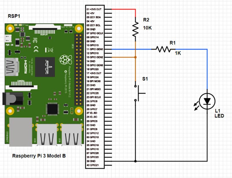
The example below shows a program that prints a message to the console when a switch connected to GPIO0 is pushed.
#include <iostream>		// Include all needed libraries here
#include <wiringPi.h>

using namespace std;		// No need to keep using “std”

void switchInterrupt(void);	// Function prototype

int main()
{
wiringPiSetup();			// Setup the library
pinMode(0, OUTPUT);		// Configure GPIO0 as an output
pinMode(1, INPUT);		// Configure GPIO1 as an input

// Cause an interrupt when switch is pressed (0V)
wiringPiISR (1, INT_EDGE_FALLING, switchInterrupt) ;

// Main program loop
while(1)
{
// Toggle the LED
digitalWrite(0, !digitalRead(0));
delay(500);
}

return 0;
}
// Our interrupt routine
void switchInterrupt(void)
{
	cout << “Button pressed” << endl;
}
Timing
The WiringPi library has many timing functions that can be useful for timing and making delay functions.
UNSIGNED INT MILLIS (VOID) AND UNSIGNED INT MICROS (VOID)
This function returns the number of milliseconds since your program last called the wiringPiSetup function. The use of this function can be helpful when determining how long it took to complete an action or time an event.
For example, this function can be called, and its value stored to an initial variable. Some actions are performed - like sending data and reading a pin state - and then this function can be called again. The difference between the two values tells you how long those actions took in milliseconds. The micros() function does the same except it returns the number of microseconds. The example below prints to the console the time difference between button presses.
#include <iostream>		// Include all needed libraries here
#include <wiringPi.h>

using namespace std;		// No need to keep using “std”
unsigned int prevTime;		// Temporary variable that holds the previous millis value

int main()
{
wiringPiSetup();			// Setup the library
pinMode(1, INPUT);		// Configure GPIO1 as an input

// Main program loop
while(1)
{
	// Wait for button to be pressed
	while(digitalRead(1));

	// Record the current time
	prevTime = millis();

	// Wait for the button to be released
while("digitalRead(1));

cout << “Time interval: “ << millis() – prevTime << endl;
}
return 0;
}
VOID DELAY (UNSIGNED INT HOWLONG) AND VOID DELAYMICROSECONDS (UNSIGNED INT HOWLONG)
These two functions are used for delays and the delay() function was used in the previous. The delay() function takes a number and will delay for that many milliseconds. The delayMicroseconds() function does the same, except it delays for that many microseconds.
#include <iostream>		// Include all needed libraries here
#include <wiringPi.h>

using namespace std;		// No need to keep using “std”

int main()
{
wiringPiSetup();			// Setup the library
pinMode(0, OUTPUT);		// Configure GPIO0 as an output

// Main program loop
while(1)
{
// Toggle the LED
digitalWrite(0, !digitalRead(0));

// Delay for 500ms
delay(500);
}
return 0;
}
PWM – Pulse Width Modulation
The Raspberry Pi has one hardware PWM pin (GPIO1) that can be controlled via WiringPi but it appears that the frequency of the PWM signal cannot be altered. However, this should have little effect on any connected circuit since PWM is often used for generating analog voltages or controlling devices. To use PWM with the PWM pin, the pin needs to be configured as “PWM_OUTPUT” in the pinMode() function. To set the desired PWM value to the pin the function pwmWrite() is used whereby the first variable passed is the PWM pin and the second variable is the value (0 to 1024).
#include <iostream>		// Include all needed libraries here
#include <wiringPi.h>

using namespace std;		// No need to keep using “std”
unsigned int prevTime;		// Temporary variable that holds the previous millis value

int main()
{
wiringPiSetup();			// Setup the library
pinMode(1, PWM_OUTPUT);		// Configure GPIO1 as an output for PWM

// Main program loop
while(1)
{
	for(int i = 0; i < 1024; i++)
	{
		pwmWrite(1, i);
		delay(1);
	}
}
return 0;
}

Have questions or comments? Continue the conversation on TechForum, DigiKey's online community and technical resource.
Visit TechForum


 中国
中国