Understanding the Nuances of an IoT Antenna Datasheet
When you’re designing a wireless Internet of Things (IoT) product, you’ll need to get to grips with antennas and their role as the sole interface between the product and the outside world. With the wrong choice of antenna, your final product may communicate, but its performance will be so compromised that users might give up on it and turn elsewhere.
The problem for many designers is that there seems to be a staggering array of antenna solutions, making the selection process somewhat daunting. So, how do you narrow down the best antenna choice for your design?
Some decisions are easier than others. Start by looking for an antenna optimized for your design’s operating band. For example, if the product uses LoRa connectivity and targets the U.S. market, the antenna should be optimized to operate in the 902 to 928 megahertz (MHz) band. If the device supports dual-band Wi-Fi, the antenna should be optimized to operate in both the 2.4 gigahertz (GHz) and 5 GHz RF bands.
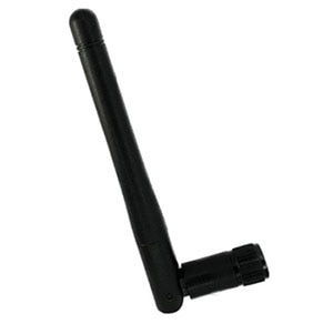
Next, consider the form factor of the final product. For example, if a Bluetooth Low Energy (LE) enabled sensor needs to be highly compact, then a good option could be Amphenol’s ST0147-00-011-A, a 2.4 GHz surface-mount chip antenna. It measures just 3.05 x 1.6 x 0.55 millimeters (mm) and is mounted directly on the device’s pc board. An example of a much larger device is a Wi-Fi access point (AP). It offers plenty of space for the antenna while satisfying the demand for good range and high throughput. A good option here is Amphenol’s ST0226-30-002-A external whip antenna (Figure 1).
 Figure 1: The ST0226-30-002-A external whip antenna suits applications such as dual-band Wi-Fi access points. (Image source: Amphenol)
After operating bands and form factors, things get a little more complex. Selecting an antenna that meets power consumption, reliability, range, and throughput specifications demands a reasonable understanding of the datasheet.
Under the hood
Take a typical datasheet, such as that for Amphenol’s ST0224-10-401-A (Figure 2). This is a Wi-Fi trace RF antenna that suits smart meter and Industrial IoT (IIoT) applications and can be mounted internally. The datasheet includes information about the device’s radiation pattern, maximum power transfer, frequency response, gain, and efficiency. Let’s consider the meaning of each of these parameters.
 Figure 2: The ST0224-10-401-A Wi-Fi trace RF antenna can be mounted internally and suits smart meter and IIoT applications. (Image source: Amphenol)
Radiation pattern: This graphically defines how the antenna radiates (or absorbs) radio-frequency (RF) energy in 3D space. The datasheet typically shows two or three slices through the 3D radiation pattern, one showing peak radiation in the XY plane and the other showing the peak in the ZY (and/or ZX) plane (Figure 3). Often, the plane patterns are referred to as the “azimuth” (XY plane) and the “elevation” (orthogonal to the XY plane, for example, across the ZY plane) when the antenna is mounted as it is intended to be used in the final product.
 Figure 3: Shown are the peak radiation patterns for a Wi-Fi trace antenna in the XY plane (left), and the ZY plane (right). (Image source: Amphenol)
An omnidirectional antenna, such as a dipole antenna, is one that radiates or receives radio energy relatively equally in all directions. This suits many IoT applications because the developer often needs to ensure connectivity between devices in any orientation relative to each other. The datasheet for the Amphenol ST0224-10-401-A antenna shows that it is an omnidirectional device.
The downside of an omnidirectional antenna is that transmission energy is dissipated across the surface of an expanding sphere, attenuating the signal strength exponentially and impacting range. In contrast, directional antennas use techniques such as beamforming to focus radio energy in a specific direction, boosting range.
Maximum power transfer: This occurs when the impedance of the transmission line (Z0) equals that of the antenna (Za). Even with well-designed impedance matching circuitry, some power is typically reflected by the antenna back along the transmission line. A common measure of how well the Z0 and Za impedances are matched is the voltage standing wave ratio (VSWR). A VSWR of 1 indicates no impedance mismatch loss, while higher numbers indicate increasing losses.
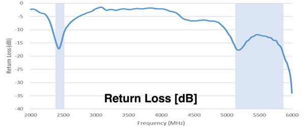
For example, a VSWR of 3.0 indicates about 75% of the power is delivered to the antenna. The power ratio of the reflected wave to the incident wave is called the return loss (RL). This indicates the reduction in decibels (dB) of the reflected wave power below that of the incident wave. A VSWR below 1.5 (an RL of ≈ 14 dB) is a satisfactory match. The Amphenol ST0224-10-401-A-10 antenna features an RL of -10 dB when operating in the 2.4 and 5 GHz frequency bands.
Because RL is also dependent on radio frequency, the developer should check the frequency response of the antenna to ensure RL is minimized in the intended operating band (Figure 4).
 Figure 4: RL is dependent on frequency. The developer should ensure the antenna offers minimum RL at the intended operating frequency. (Image source: Amphenol)
Gain and efficiency: Gain describes how much power is transmitted in the direction of peak radiation and is usually given in dB referenced to an isotropic antenna (dBi). Gain is related to the antenna’s directivity and efficiency. Directivity measures the directional nature of the antenna’s radiation pattern. For example, a perfectly omnidirectional antenna has zero directionality and a directivity of 1 (or 0 dB). Directivity is usually quoted as the peak value according to the radiation pattern (Dmax). Gain is more commonly quoted in an antenna’s specification sheet than directivity because it takes into consideration VSWR mismatch and energy losses.
Efficiency (η) is the ratio of total radiated power (TRP, or Prad) to input power (Pin). TRP is calculated by integrating the power emitted across the entire radiation pattern. To calculate η, use the formula η = (Prad/Pin) * 100%. The antenna peak gain is then Gainmax = η * Dmax.
A transmitting antenna with a gain of 3 dB will radiate twice the power of a lossless isotropic antenna with the same input power. A lossless antenna is one with an efficiency of 0 dB (or 100%). Similarly, a receive antenna with a peak gain of 3 dB would receive twice as much power as a lossless isotropic antenna. For our Amphenol example, the peak gain is 2.1 dBi in the 2.4 GHz band and 3.1 in the 5 GHz band.
High gain is not always a good thing. If the direction of the incoming signal is unknown, then it’s better to have a low gain (low directivity) antenna to ensure a satisfactory response to signals from all directions. An example is the antenna on a smartphone. This needs to be low gain because the incoming and outgoing signals to the nearest cellular basestation come and go in an arbitrary direction.
Conclusion
The antenna is a critical component of an IoT product. The wrong choice can dramatically compromise the performance of the wireless device. Some parts of the selection process, such as matching the antenna to the operating frequency and selecting an antenna that fits the space available, are straightforward. The key to choosing the correct antenna is understanding the terms used in the datasheet and paying particular attention to radiation pattern, maximum power transfer, frequency response, and gain.

Have questions or comments? Continue the conversation on TechForum, Digi-Key's online community and technical resource.
Visit TechForum


 中国
中国