What are Some Key Considerations When Selecting Industrial Automation Equipment?

作者:Jeff Shepard

投稿人:DigiKey 北美编辑

Optimal selection of industrial automation equipment like motors, drives, and communications modules requires careful attention to detail. For example, there are numerous differences between the National Electrical Manufacturers Association (NEMA) in North America and the International Electrotechnical Commission (IEC) in Europe regarding motor and drive ratings.

When selecting motors, drives, and controllers, some considerations include the input and output voltages and tolerances, required speed range and regulation needs, torque requirements, acceleration, braking duty cycles, special needs like quick speed or torque response, and environmental factors, including thermal management.

Communication needs vary depending on where the equipment is in the industrial control hierarchy. At the level nearest the edge of the factory floor, protocols like IO-Link can be used for intelligent sensors and actuators, and EtherCAT, PROFINET, Modbus, and other protocols can connect motion, safety, I/O, and vision.

The highest level of the factory automation network often uses Ethernet/IP to connect with various automation controllers, programming interfaces, and the cloud, as well as a protocol like DisplayPort to connect with human machine interfaces (HMIs). In between, combinations of Ethernet/IP, EtherCAT, and other protocols can link the factory floor's field level to the operation and control levels.

The details are too numerous to do them justice in a single discussion. Instead, this article presents several guideposts to consider when specifying motors, drives, and communications modules, along with examples of application, hardware, and protocol from Siemens, Phoenix Contact, Omron Automation, Panasonic Industrial, and Schneider Electric.

Shifting focus

Motors and drives are a common thread across many industrial automation systems. As a starting point for this discussion, it’s helpful to see where motor efficiency fits into the wider considerations of industrial automation system performance and how the focus is shifting.

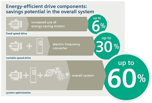
Using higher-efficiency motors can produce energy savings of up to 6%. That’s good. However, adding a high-efficiency drive along with support components can boost energy savings by up to 30%.

A real game-changer occurs when the focus is shifted to overall system optimization. Considering all the mechanical components and adding communication to tie into the Industrial Internet of Things (IIoT), including the operational and plant levels and ultimately to the enterprise level, as well as the cloud, can result in up to 60% energy savings plus higher productivity (Figure 1).

Image of energy savings and higher productivityFigure 1: Increasing levels of integration and communication result in more energy savings and higher productivity. (Image source: Siemens)

Ecodesign for motor systems

Part 2 of IEC 61800-9, “Ecodesign for motor systems - Energy efficiency determination and classification,” can be a key resource. Instead of focusing solely on motor efficiency, it details a series of higher-level performance factors for “electric motor-driven systems.” VFDs are considered in the context of a complete drive module (CDM) that includes the AC input ‘” feeding section,” a “basic drive module” (BDM) like a VFD, and “auxiliaries” that include input and output filters, line chokes, and other support components.

The standard also defines a power drive system (PDS) as the CDM plus the motor. Next up the hierarchy, the standard describes the motor system as the PDS plus motor control equipment like contactors.

At the highest level is the extended product, or overall system in Figure 1, which adds mechanical drive equipment like a transmission and the load machine. For a more detailed review of IEC 61800-9-2 PDS efficiency standards, check out the article “What are the different types of adjustable speed industrial motor drives?

The starting point for specifying “electric motor-driven systems” is the motor.

Motor matters

Electric motors can be highly efficient machines if properly specified and used. That makes specifying motors an important task for machine designers.

The IEC quantifies motor power in kilowatts (kW), while NEMA uses horsepower (hp), which can be easily equated. However, IEC and NEMA use different efficiency calculations, and IEC nameplate efficiency can be slightly higher than the NEMA rating for the same motor design.

Actual motor efficiency is strongly tied to the specific use case. As a result, motor efficiency standards are often discussed in terms of reductions in energy losses rather than absolute efficiency.

IEC 60034-30-1 recognizes five motor efficiency classes, from IE1 to IE5. Energy losses decline 20% between classes. That means an IE5 “Ultra Premium” motor has 20% lower losses than an IE4 “Super Premium” motor. There’s more to consider. In some cases, the power factor (PF) declines for motors with higher efficiency.

In North America, NEMA has fewer energy efficiency classes, which are just as important. NEMA recognizes motor service factors (SF) not included in IEC standards. A NEMA motor with an SF of 1.15 can be run continuously at 115% of its rated capacity, albeit the motor runs hotter, which can result in reduced bearing and insulation life.

Instead of SF, IEC recognizes ten duty types or service factors (S1 to S10) based on considerations like continuous versus intermittent operation, speed variations, and the use of braking.

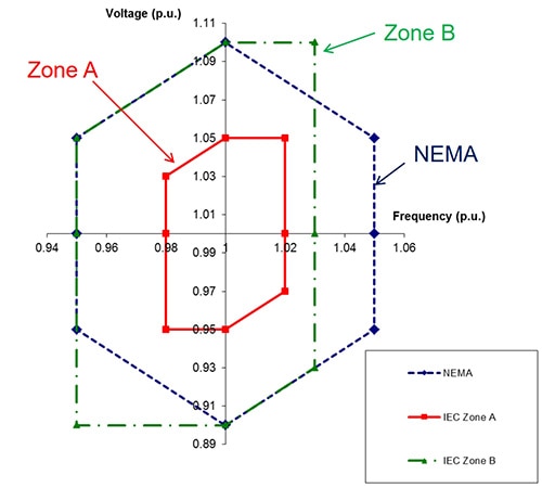
Operating voltage and frequency ranges differ for NEMA and IEC, but both are expressed as “per unit” (p.u.) quantities. In the p.u. system, quantities are expressed as fractions of the base value. NEMA recognizes one range of motor voltages and frequencies. IEC recognizes two “Zones” (Figure 2).

Image of NEMA and IEC industrial AC voltage and frequency rangesFigure 2: Comparison of NEMA and IEC industrial AC voltage and frequency ranges. (Image source: NEMA)

Driving for PDS efficiency

Motor drives are key elements of PDS efficiency as defined in IEC 61800-9-2. They can be classified in several ways, such as motor voltage, power level, motion types, supported applications, etc. Motion types can be classified as continuous or discontinuous. They can be further categorized as low, medium, and high performance based on the maximum required power output.

Different types of drives support various system needs. Servo drives and motors are well suited when fast acceleration, deceleration, and precise positioning are needed in applications like robotics. Soft starters are suited for continuous operations like conveyors that benefit from smooth startup and deceleration. VFDs are used in a wide range of industrial machines.

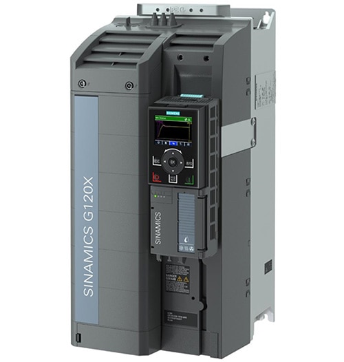
Some VFD product families are optimized for operations like pumping, ventilating, compressing, moving, or processing. Siemens SINAMICS G120 line of universal drives are available with power ratings from 0.55 to 250 kW (0.75 to 400 hp) for use in general industrial applications in automotive, textile, and packaging operations.

Model 6SL32203YE340UF0 uses 3-phase power with an operating voltage range of 380 to 480 Vac +10 % / -20 %. It’s specified for 400 V operation with motors rated from 22 to 30 kW in Europe and 480 V in North America for motors rated from 30 to 40 hp (Figure 3).

Image of Siemens 6SL32203YE340UF0 3-phase power converterFigure 3: This VFD can be used with motors rated from 22 to 30 kW, depending on the operating voltage. (Image source: DigiKey)

VFDs are not the only key to efficient PDS design. The article “What support products does it take to maximize the impact of using VFDs and VSDs? - Part 1” reviews some of the required support components.

Communication and system optimization

While motors and drives are on the factory floor in Level 1, or the field level, they are not at the lowest level of the Industry 4.0 communication hierarchy. That position falls to functions like sensors and actuators on Level 0. In addition, there are multiple levels above the field level. Timely and efficient communication up and down the communication hierarchy up to the cloud is necessary to maximize the overall efficiency, productivity, and sustainability of Industry 4.0 factories. Cloud connectivity is facilitated using protocols like (Figure 4):

  • uOPC PubSub Bridge consolidates multiple operational technology (OT) data streams.
  • MOTT BRoker receives messages and forwards them to users based on the message subject.

Image of Industry 4.0 communications hierarchyFigure 4: All levels of the Industry 4.0 communications hierarchy have the possibility of connecting directly to the Cloud. (Image source: OPC Foundation)

There’s more to Level 1 than drives and motors. Field bus master units (FMUs) can facilitate communication and simplify the integration of drives and other devices. FMUs are available for various protocols, including PROFINET, PROFIBUS, DeviceNet, CANopen, etc. The use of FMUs can enable manufacturer-independent connectivity.

Model AFP7NPFNM from Panasonic is a PROFINET FMU. It comes with integrated function libraries for the programming software, significantly reducing the time needed to develop application-specific solutions.

Level 0 for sensors, actuators, and safety

Pushing the PDS energy savings gains from VFDs higher requires pushing connectivity lower to Level 0. Integrating sensors, actuators, and safety devices like light curtains on Level 0 can significantly enhance efficiency improvements and push energy savings up beyond 30%.

Common protocols used to connect Level 0 functions include DeviceNet, HART, Modbus, and IO-Link. IO-Link is a point-to-point protocol that connects sensors and actuators to higher-level controls. It’s available as a wired or wireless standard and is increasingly deployed in Industry 4.0 as a cost-effective alternative.

The NX-ILM400 IO-Link master units from Omron can mix standard I/O with high-speed synchronous I/O. The standard digital I/O’s have 16 connections per unit with a choice of (Figure 5):

  • Four 3-wire sensor connections with power supply
  • Eight 2-wire contact inputs or actuator outputs
  • Sixteen 1-wire connections for sensors and actuators connected to a common power supply

Image of Omron Automation IO-Link master unitFigure 5: This IO-Link master unit supports standard and high-speed synchronous I/O. (Image source: Omron Automation)

Level 2 for PDS and beyond

Higher-level communications can help improve field-level operations, but they are mandatory to maximize organizational efficiency and productivity. Reaching from Level 2 up to Levels 3, 4, and the cloud requires protocols like Ethernet/IP, EtherCAT, and Modbus TCP/IP.

Equipment possibilities for making those connections include programmable logic controllers (PLCs) or industrial personal computers (IPCs). PLCs are computers optimized for industrial automation and control. In a typical application, a PLC monitors inputs from the machine and related sensors, makes decisions based on its programming, and sends control outputs.

While IPCs can perform functions like PLCs, they are more general-purpose devices. They run an operating system like Linux or Windows, giving them access to an array of software tools, and are usually connected to an HMI (many PLCs can also connect to HMIs). PLCs tend to be machine-focused, while IPCs have more operational functions.

The differences between PLCs and IPCs are blurring. For example, the 1069208 PLC from Phoenix Contact runs the Linux operating system. Like traditional PLCs, it can be programmed with symbolic flowchart (SFC), ladder diagram (LD), function block diagram (FBD), and structured text (ST). It includes three independent Ethernet interfaces and can connect to the PROFICLOUD.

Schneider Electric offers the HMIBMIEA5DD1E01 IIoT Edge Box for applications that can benefit from an IPC. This fan-less design includes an Intel Atom Apollo Lake E3930 dual-core processor running at 1.8 GHz. It has a mini PCIe expansion slot and nine communication ports (Figure 6).

Image of Schneider Electric Harmony fanless IPC with a mini PCIe expansion slotFigure 6: Fanless IPC with a mini PCIe expansion slot and multiple communication options. (Image source: Schneider Electric)

Conclusion

This article has provided a brief overview of some guideposts designers should consider when specifying motors, drives and communications modules for Industry 4.0 installations. It’s far from exhaustive. It is intended to provide food for thought and some resources for further investigation.

免责声明:各个作者和/或论坛参与者在本网站发表的观点、看法和意见不代表 DigiKey 的观点、看法和意见,也不代表 DigiKey 官方政策。

关于此作者

Jeff Shepard

Jeff 从事电力电子、电子元件和其它技术主题写作 30 余载。在其于 EETimes 任职高级编辑期间,他开始了电力电子写作。后来,他创立了一份叫《Powertechniques》的电力电子杂志,再后来又创立了一家全球性的研究和出版公司 Darnell Group。在开展各项业务的同时,Darnell Group 还发布了 PowerPulse.net,专门针对全球电力电子工程社区提供每日新闻。他是一本名为《Power Supplies》的开关模式电源教课书的作者,该书由 Prentice Hall 旗下 Reston 分部出版。

Jeff 还是 Jeta Power Systems 共同创始人,这是一家高功率开关电源制造商,后来被 Computer Products 收购。Jeff 也是一个发明家,其名下拥有 17 项热能收集和光学超材料美国专利,同时他也是掌握电力电子行业全球趋势的专家和网红发言人。他拥有加利福尼亚大学定量方法和数学硕士学位。

关于此出版商

DigiKey 北美编辑