Use Isolation to Preserve Accuracy and Enhance Performance for Data Acquisition
投稿人:DigiKey 北美编辑
2024-12-20
As intelligence migrates to the edge to solve novel and complex problems, it becomes increasingly important to ensure the reliability, accuracy, and performance of data acquisition (DAQ). This requires that designers provide an isolated precision signal chain between the acquired signal and the system processor.
Ensuring isolation in a precision analog-signal measurement chain is a challenging task. Careful attention to detail is required to maintain signal-chain performance despite signal-corrupting factors and unavoidable temperature drift. For many designers, it can be helpful to understand the issues involved better before selecting and using the appropriate isolation technology.
This article discusses the various issues associated with developing and optimizing a high-end isolated DAQ system, where the designation “high end” encompasses attributes of precision, accuracy, signal integrity, and consistency. It then introduces DAQ signal-chain solutions from Analog Devices and shows how they can be used to form such a system.
Optimizing each functional block
A typical DAQ system consists of a series of functional blocks, which allow the signal to pass from the physical system via a sensor. From there, it travels to an analog front end (AFE) for signal conditioning, an analog-to-digital converter (ADC) for digitizing, and then a computer-based readout or controller (which could range from a microcontroller to a much larger system (Figure 1).
Figure 1: A DAQ system consists of a well-defined, linear signal chain from the measured physical system and sensor to the host processor. (Image source: Bill Schweber)
Realizing DAQ precision and accuracy begins with selecting the front-end signal-conditioning components, particularly the transducer preamplifier. Low-noise performance is among the many critical factors for this function since internal noise is difficult to reduce later in the design and will be amplified along with the desired signal. A baseline signal-to-noise ratio (SNR) is established here and will unavoidably be further degraded as the signal passes through additional stages.
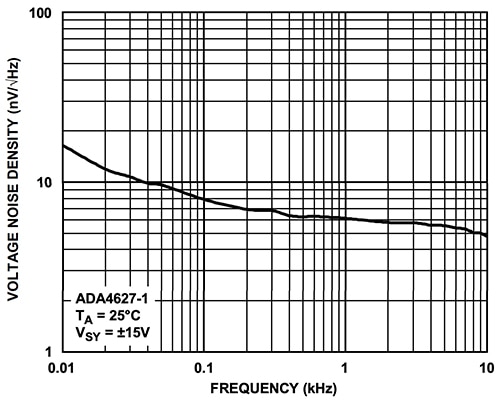
For this reason, AFEs often use a noise-optimized single-function operational amplifier (op amp). A good choice for the front-end preamplifier is the Analog Devices ADA4627-1BRZ-R7, a 30 V (±15 V dual supply), high-speed, low-noise, low-bias current JFET op amp. Among its many sensor-optimized specifications, it features a low offset voltage of 200 µV (maximum), an offset drift of 1 μV/°C (typical), and an input bias current of 5 picoamps (pA) (maximum). The critical voltage noise specification is 6.1 nV per root hertz (nV/√Hz) at 1 kilohertz (kHz) (Figure 2).
Figure 2: The ADA4627 JFET op amp features a voltage noise of 6.1 nV/√Hz (1 kHz). (Image source: Analog Devices)
Isolation brings multiple benefits
Once the signal has been amplified and digitized, the next step is establishing galvanic isolation between the signal and the system’s digital section and associated processor. There are three primary reasons for this step:
- Noise and interference reduction: Galvanic isolation can eliminate common-mode voltage variations, ground loops, and electromagnetic interference (EMI). It also prevents external noise sources from corrupting the acquired signal, ensuring cleaner and more accurate measurements.
- Ground-loop elimination: Ground loops can introduce voltage differentials that distort the measured signal. Isolation breaks the ground loop path, thus removing the interference caused by the variation of ground potentials and improving measurement accuracy.
- Safety and protection: Isolation barriers provide electrical safety by preventing hazardous voltage spikes, transients, or surges from reaching sensitive measurement components. This protects the measurement circuitry and connected devices, ensuring safe and reliable operation. In addition, such barriers eliminate the electrical hazard to users if the low-level sensor even briefly touches a high-voltage or AC line.
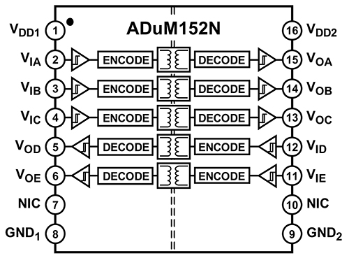
Several techniques are available to implement isolation of digital signals based on magnetic, optical, capacitive, and even RF principles. Analog Devices offers a family of high-performance solutions, including the ADUM152N1BRZ-RL7 five-channel digital isolator based on their proprietary iCoupler technology (Figure 3).
Figure 3: The ADuM152N five-channel digital isolator uses a proprietary magnetic-coupling implementation to achieve high performance. (Image source: Analog Devices)
These isolators combine high-speed CMOS circuitry and monolithic air core transformer technology. To ensure performance commensurate with the needs of high-speed digital links, the maximum propagation delay is 13 nanoseconds (ns) with a pulse width distortion of less than 4.5 ns at 5 V, and the channel-to-channel matching of propagation delay is tight at 4.0 ns (maximum). A similar two-channel version, the ADUM120N1BRZ-RL7, is available so the overall number of isolated channels can be matched to the bus width.
These isolators are optimized for high-speed performance with a guaranteed data rate of 150 megabits per second (Mbits/s). They offer a high common-mode transient immunity (CMTI) of 100 kV per microsecond (kV/μs), a withstand voltage rating of 3 kV root mean square (rms), and adhere to all relevant regulatory mandates.
Signal isolation is only part of the overall isolation story. All DC power rails to the DAQ system must also be isolated. This is most often accomplished using a transformer as the isolating element.
If the primary power source is already AC, it is passed through the transformer, then rectified and regulated; if the source power is DC, it must first be chopped to an AC-like waveform. This is greatly simplified using components such as the LT3999, a low-noise, 1 ampere (A), 50 kHz to 1 megahertz (MHz) DC/DC driver.
A complete high-performance DAQ system requires additional core and peripheral components. Their design and arrangement must ensure accurate measurement and data integrity. In addition to the amplifiers and isolation barriers, a precision signal chain typically includes filtering elements, a high-resolution ADC, and switches. These components combine to eliminate noise, minimize interference, and provide accurate signal representation.
Putting it all together
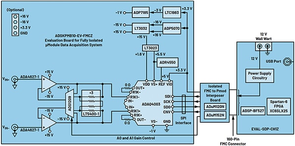
An example of an isolated signal chain using these key components is the ADSKPMB10-EV-FMCZ, a precision platform that implements a single-channel, fully isolated, low-latency DAQ system (Figure 4). This solution combines a programmable gain instrumentation amplifier (PGIA) for signal conditioning to accommodate the sensitivities of the various sensor interfaces with digital and power isolation within a compact board.
Figure 4: The ADKSPMB10-EV-FMCZ is a precision platform that implements a single-channel, fully isolated, low-latency DAQ system. A PMOD-to-FMC interposer board (center block) provides isolation and other functions. (Image source: Analog Devices)
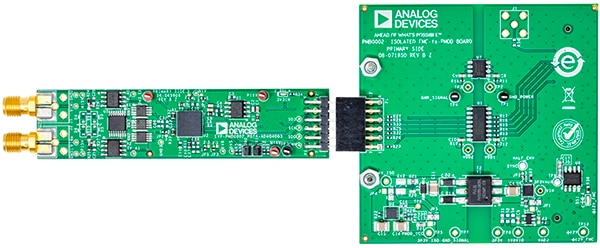
For evaluation, this is configured as a multi-board solution consisting of the ADSKPMB10-EV-FMCZ on a PMOD form factor (Figure 5) along with the EVAL-SDP-CH1Z system demonstration platform (SDP) interface board. Between these two boards is a fully isolated PMOD-to-FMC interposer board.
Figure 5: The ADSKPMB10-EV-FMCZ (left) connects to the SDP interface board (not shown) via the PMOD-to-FMC interposer board (right). The vertical split zone on the interposer board shows where the isolation barrier is implemented. (Image source: Analog Devices)
The ADSKPMB10-EV-FMCZ features a discrete PGIA built using the ADA4627-1 op amp. The PGIA has the high input impedance necessary to support direct interfacing with a variety of sensors. The module also features a precision quad matched-resistor network for gain setting, a quad-channel multiplexer, and a fully differential amplifier ADC driver for the ADAQ4003. The ADAQ4003 is an 18-bit, 2 megasamples per second (MSPS) ADC and DAQ subsystem implemented as a μModule.
This module is more than just a high-resolution ADC. Multiple noise-reduction techniques are incorporated in the ADAQ4003 to enable high-fidelity signal capture. For example, a single-pole, low-pass resistor-capacitor (RC) filter is placed between the ADC driver output and the ADC inputs inside the μModule to eliminate high-frequency noise and reduce the charge “kickbacks” from the input of the internal ADC.
Further, the layout of the μModule ensures that the analog and digital paths are separated to avoid crossover and minimize radiating noise.
The fully isolated PMOD-to-FMC interposer board includes the LT3999 DC/DC driver, the five and two-channel digital isolators, a low-noise low-dropout regulator (LDO), and an ultra-low-noise LDO. The interposer board functions as a bridge and connects to the SDP interface board.
The SDP interface board performs post-acquisition processing, management, and connectivity. This board has a 160-pin FMC connector, a 12 VDC power supply, which is further regulated and partitioned for the other boards, a Blackfin processor with hardware-enabled security for code and content protection, a USB port, and a Spartan-6 FPGA.
The proof is in the performance
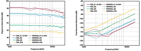
Assessing the performance of a precision DAQ system is not a trivial process, as the instrumentation, test arrangement, and metrics are critical. While many dynamic parameters correlate to the performance of DAQ systems, the most revealing are dynamic range, signal-to-noise ratio (SNR), and total harmonic distortion (THD).
Dynamic range is the range between the noise floor of a device and its specified maximum output level.
This design's typical dynamic range of 93 decibels (dB) at the highest gain setting and 100 dB at the lowest gain setting is impressive (Figure 6). Increasing the oversampling ratio to a factor of 1024× further improves the measurement, reaching a maximum of 123 dB and 130 dB, respectively.
Figure 6: The approximately 100 dB dynamic range of the complete circuit and signal chain, depending on gain and other settings, indicates a high-performance DAQ system. (Image source: Analog Devices)
SNR is the ratio of the rms signal amplitude to the mean value of the root-sum-square (RSS) of all other spectral components, excluding harmonics and DC. THD is the ratio of the rms value of the fundamental signal to the mean value of the RSS of its harmonics.
The SNR and THD for this design are clearly high performance, as the signal chain achieves a maximum SNR of 98 dB (Figure 7 (left)) and a THD of –118 dB (Figure 7 (right)), depending on gain settings.
Figure 7: Along with the dynamic range, the high SNR (left) and the low THD (right) provide tangible evidence of superior analog-focused DAQ performance.(Image source: Analog Devices)
Conclusion
Designing and implementing an isolated precision signal chain that preserves accuracy, minimizes noise and interference, and ensures data integrity is a significant design and implementation undertaking. Fortunately, it can be accomplished through judicious use of precision amplification, isolation techniques, high-resolution ADCs and modules, and low-noise power management to enable precise measurements, even in electrically challenging environments. This is made possible by using advanced components from Analog Devices ranging from basic op amps to advanced isolation devices, and supported by necessary peripheral functions, along with detailed data sheets and application guidelines.
免责声明:各个作者和/或论坛参与者在本网站发表的观点、看法和意见不代表 DigiKey 的观点、看法和意见,也不代表 DigiKey 官方政策。