Tamper Protection Secures Your Valuable MCU-Based System IP
投稿人:电子产品
2015-08-12
MCU-based designs make it easy to add specialized and differentiated functions by coding the algorithms into the device. A new twist on an older algorithm or a completely new approach can make the difference between a successful product and a failure. Unfortunately, using an MCU can also open up your design to reverse engineering, where a competitor steals your hard work and benefits from your innovations. Sure, lawyers can get involved and perhaps retaliate, but often only after the damage has been done. A better approach is to protect your design from common hardware tampering intrusions that are used to gain access to your code and steal your valuable IP.
This article will describe some of the common approaches hardware “hackers” use to gain access to your valuable design IP. New MCUs include several key functions that can be used to put some difficult barriers in place to prevent hardware tampering. These tamper-protection design techniques can become an important part of an MCU designer’s technical “bag of tricks.”
On-chip tamper prevention: supervisor mode
One of the more recent innovations in MCUs has been the inclusion of a feature that has been used in standard CPUs for many years. One of the earliest tamper-prevention features, separating the user-operating mode from the supervisor-operating mode (the supervisor mode is often associated with the operating-system mode in CPUs) has been showing up in MCU devices. This capability allows supervisory software to have privileged access to protected resources while limiting or eliminating access to less privileged user programs. This makes it much more difficult for a hacker to gain control of the system via user software code bugs. Even if a user bug can be used to gain control of the MCU, it will still be stuck in the user mode without access to the most important system elements related to configuration, programming, debugging, and system control.
As an illustrative example, the Freescale Kinetis K60 MCU family supports both a supervisor and user mode. This allows the system to retain control over configuring peripherals, accessing protected memory space, restricting re-programming of system code, and restricting access to cryptographic functions used to protect user data. Many of the key MCU-system resources require a supervisory mode for access to configuration registers. The multi-purpose clock generator (MCG), for example, limits write access to all the associated control registers to the supervisor mode (Figure1). This eliminates the possibility of unauthorized tampering with the clock settings, a potential attack vector by a hardware hacker attempting to disable system operation. Additionally, the supervisor mode keeps user code from inadvertently accessing system resources and then potentially providing an attacker with a convenient “back door” to gain access to otherwise protected resources.

Figure 1: Freescale Kinetis K60 MCU Multi-purpose Clock Generator Features Supervisor-Only Write Access to Sensitive Control Registers (Courtesy of Freescale)
Many other peripherals and system functions have similar access protection. The most sensitive elements, like the flash-memory controller, limit write access to control and data registers to supervisor mode only. The cache memory in the flash-memory controller is even protected from unauthorized reading so a hacker cannot “snoop” otherwise sensitive data. Other less sensitive elements have less stringent access requirements, but even the CAN bus control registers can be protected against unauthorized writes, since you do not want a hacker to be able to control the brakes on your car!
Tamper-detection features
No matter how thorough you are in protecting your design there is still the possibility that tampering may occur. Several approaches to tamper detection are possible and often simple to implement. For example, in order to detect board-level tamper events (such as hardware probing, lifting-signal traces, and power supply alterations) it is common to place special hidden tamper-detection traces in internal layers on the printed circuit board. If an attacker attempts to drill the circuit board to access key signals, the effects on the hidden traces can be detected. Another common approach is to use a mechanical tamper-detection cover that can detect an attacker’s attempt to access the enclosed devices.
Most tamper-detection approaches can generate a tamper-detection signal and it’s up to the MCU to then take action—usually very quickly so the attacker has little time available for mischief. Common actions an MCU might take when a tamper event is detected is to quickly log the event and then reset the system, turn off power to critical sections, or even erase sensitive information. Logging the event can be a useful way to gradually escalate the “penalty” tampering generates. If tampering is a recurring event then it might be prudent to apply a more severe response, perhaps erasing code and sensitive data. If this is the first tampering event, a less severe response, perhaps just a system reset, might be more appropriate. Capturing a time stamp for the tampering event is important if the log will be used for determining the escalation procedure.
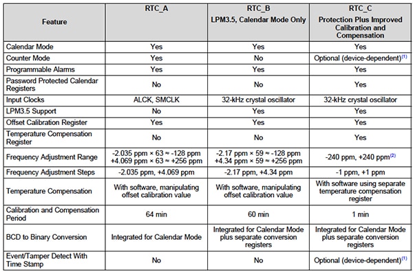
Some MCUs include a capability to monitor an event input and generate a time stamp for use in logging. The Texas Instruments MSP430FR5739 MCU, for example, has a real-time clock peripheral (RTC), RTC_C, that is similar to other RTC peripherals, as shown in Figure 2 below. However, RTC_C has an additional tamper-detect event logging capability.

Figure 2: Texas Instruments MSP430 Timer/Counter Resources (Courtesy of Texas Instruments)
The Event/Tamper detect time stamp can monitor two MCU inputs and when either becomes active a tamper event is generated. The inputs could come from switches used to detect the removal of a tamper-protection cover, removal of the back-up battery or any number of ingenious hidden tamper-detection methods. The value of the real-time clock is captured when a tamper event is activated and it can be used as part of a logging activity. This value can be used to see if tamper events are occurring with an increased frequency so that escalating penalties can be applied.
Tamper reporting with an event-monitor recorder
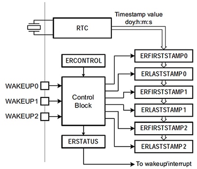
In order to simplify the process of capturing and recording tamper events, some MCUs add even more functionality to the tamper-event detection and time-stamp capture function. For example, the NXP LPC1800 MCU has a dedicated event monitor/recorder peripheral available to quickly capture, record, and respond to tamper events. As seen in the block diagram in Figure 3, the NXP LPC1800 monitors up to three tamper-event inputs and can capture time stamps for the events. Time stamps are stored for the first tamper event and the last tamper event, making it easy to see the period over which they occurred. The entire peripheral operates off the back-up battery power domain, as does the RTC, making it possible to record events even if they happen as power is being removed or during a power-off situation—a common approach used by hackers to try and circumvent enclosure-based tamper-detection schemes.

Figure 3: NXP LPC1800 MCU Family Event Monitor Recorder Block Diagram (Courtesy of NXP)
Note that even if the MCU is in a low-power state an interrupt or wake-up event can be generated. This makes certain that tamper events can be responded to quickly, so that hackers have a minimum amount of time to attack the system prior to penalties being applied. As security and tamper detection and prevention become increasingly important, expect even more features to be added to specialized tamper peripherals so that designs can be protected with even less overhead.
Reference designs show you the way
One of the most powerful ways to learn about tamper detection and prevention features for MCU designs is to look at reference designs. Many MCU suppliers provide reference designs for their products and in some cases they illustrate advanced features, such as tamper detection and prevention. As just one example, Microchip has an energy-meter reference design that is very close to a complete system based on the PIC18F MCU. Part of the design includes several tamper-detection features, including power reversal, frequency disturbance, low current, externally applied magnetic-field detection, and a tamper-cover removal detection switch. Figure 4 below shows the system and the list of tamper codes that are logged when tamper events are detected.

Figure 4: Microchip Energy Meter Reference Design and Anti-Tamper Features (Courtesy of Microchip)
The hardware layout, schematics, and bill of materials are available to leverage much of the work that Microchip put into the reference design. The code is also available and can be used as a starting point for your own tamper detection and logging scheme for a Microchip PIC 18F MCU-based design. You also can use the DigiKey Reference Design Library and search for “Tamper” to easily generate a list of reference designs that feature tamper-related functions.
Conclusion
The use of anti-tamper techniques can be critical to protect valuable design IP created for MCU-based systems. Several anti-tamper techniques are available in modern MCU devices and can be effective at hindering even the most aggressive hardware hackers.
For more information about the parts discussed in this article, use the links provided to access product pages on the DigiKey website.
免责声明:各个作者和/或论坛参与者在本网站发表的观点、看法和意见不代表 DigiKey 的观点、看法和意见,也不代表 DigiKey 官方政策。


 中国
中国