Selecting an MCU for Intelligent Power Control Applications
投稿人:电子产品
2015-09-09
Power supplies continue to provide new features to improve efficiency, safety, and manageability in demanding communications, industrial, and medical applications. Increasingly, MCUs are a key element in these intelligent power supplies and implement a wide range of control, sensing, and management functions. A look at some of the more advanced MCU hardware features and the ways they simplify the design of intelligent power supplies will be useful for any hardware designer working with embedded systems.
This article will illustrate several of the key MCU features available to embedded designers that address intelligent power supply requirements. Control of the power supply during start-up conditions is one obvious requirement, but sensing, logging, and communicating power supply operations is perhaps the area where MCU capabilities are best applied.
Reliability, safety, and efficiency
Today reliability, safety, and efficiency are the key customer concerns for most power supply subsystems. However, these requirements often conflict with the traditional concerns of low cost, small board space, and ease of design. Using an advanced MCU as the controller for an intelligent power supply design can help mitigate some of these conflicts to create a more optimized design. Modern MCUs pack significant capabilities in a small board space, with little cost and the availability of reference designs, code examples, and development platforms dramatically simplify implementation.
Usually the MCU needs some external supporting devices to complete the design. Finding the correct combination of the right MCU and the right external devices is key to efficient implementations. A quick look at some important on-chip MCU functions and some of the common external devices that pair efficiently with an MCU will help guide you to your own device selections for an efficient implementation based on your custom requirements.
One of the most significant trends that have helped position MCUs as efficient power supply controllers has been the development of standard interfaces within power supply applications. For example, the evolution of I2C and SPI buses as industry standards for MCU peripheral devices has made it easy to “build out” common subsystems and leverage standard drivers and higher-level software functions. Flash memories, analog-to-digital converters, digital-to-analog converters, temperature, voltage, and current sensors can all share a common SPI or I2C bus, and thus reduce pin-count requirements and simplify software design.
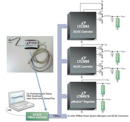
The Power management Bus, or PMBus is another industry-standard serial interface and has been developed with power supply control in mind. This bus is based on the I2C standard but includes some feature-specific capabilities to simplify the communication with common supply elements such as measured current levels, voltage levels, temperatures, and fan speeds. The bus has enabled the development of DC/DC controllers, regulators, and interface devices that dramatically increase the potential intelligence of an MCU-based power supply subsystem. Examples of some PMBus-oriented DC/DC controllers and regulators from Linear Technology (such as the LTC3883) are shown in Figure 1 below.

Figure 1: Linear Technology PMBus block diagram. (Courtesy of Linear Technology)
Along with a variety of DC/DC controllers and regulators, Linear also has the DC1613 PMBus controller, shown in the upper left of Figure 1. This interface plugs directly into a laptop and an SMBus connector. When used in conjunction with the LTC supplied LTPowerPlay software the part can be used to quickly test and configure PMBus devices to accelerate system development. LTC also supplies an evaluation kit, the DC1778A, which can be used to explore the use of the PMBus-based DC/DC controllers like the LTC3883.
Most modern MCUs directly support the PMBus standard and this makes it easy to implement the intelligence required for advanced power supply subsystems. For example, the NXP LPC11xx MCU has a serial peripheral controller that can implement the PMBus and an application note1 explains how to implement the PMBus software stack. Look for these types of resources that simplify code development—they are invaluable in speeding MCU-based implementations.
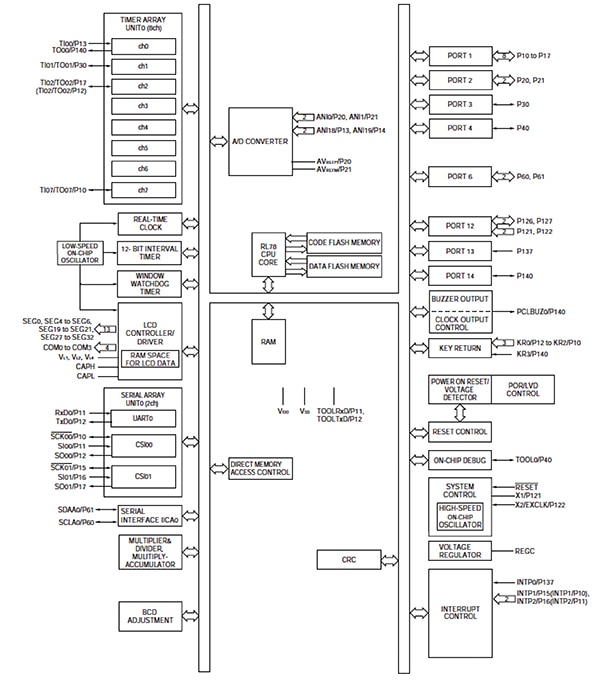
In addition to on-chip PMBus support some other common power supply requirements can help drive your choice of an MCU controller. Often pulse-width modulation, or PWM, techniques are used for controlling voltage and/or current in intelligent power supply designs. For example, setting the duty cycle for the “on time” of a current control MOSFET switch is typically done with a PWM-capable timer peripheral so the MCU need not spend significant CPU cycles managing the MOSFET control output. Some MCUs have on-chip analog-to-digital converters and digital-to-analog converters that can be useful in sensing temperatures and controlling voltages to analog peripherals. The ability to quickly store non-volatile data on-chip is another helpful capability when data logging is desired to track power subsystem performance. The Renesas RL78 MCU , shown in Figure 2 is one example of a modern MCU with many of the on-chip capabilities identified so far. An extensive array of timers, with PWM capabilities, on-chip data flash, analog-to-digital converter, and a serial interface that supports the PMBus can all be used to advantage in intelligent power supply designs.

Figure 2: Renesas RL78 MCU block diagram. (Courtesy of Renesas)
Renesas also provides an application note and sample code that illustrates how to implement the PMBus for the RL78/I1A. The example code shows how to support a PMBus transmission/reception on the I2C serial interface. The code is available in C and the example uses the Renesas CubeSuite+ IDE.
External device support
Typically the MCU cannot provide all the functionality required in implementing a power supply subsystem. For example, external high-power MOSFET devices used to switch on and off the large currents required are most efficiently implemented as stand-alone devices. Integrating these devices on-chip is usually more costly than using dedicated devices, so you will most often use at least a few external MOSFETs or IGBTs and perhaps a specialized driver in your design. Some MOSFET drivers integrate control and monitoring logic on-chip and this can make designs easier and more intelligent. For example, the STMicroelectronics PM8834 is a dual low-side driver suitable for charging and discharging large capacitive loads like MOSFETs or IGBTs. The block diagram of the PM8834 is shown in Figure 3 below.

Figure 3: STMicroelectronics PM8834 block diagram. (Courtesy of STMicroelectronics)
The enable pins make it easy to override the PWM control inputs during error conditions, improving safety and reliability. Furthermore, the UVLO block, in the middle of the block diagram, helps control the ramp-up of the drivers (it keeps the drivers off until the UVLO threshold is reached). For VCC voltages greater than the UVLO threshold (UVLOVCC), the PWM input keeps the control of the driver operations, provided that the corresponding enable pin is active. Both PWM_1 and PWM_2 are internally pulled down so, if left floating, the corresponding output pins are discharged. Simple, but useful, features like these can simplify coding and also enhance the reliability and safety characteristics of the design.
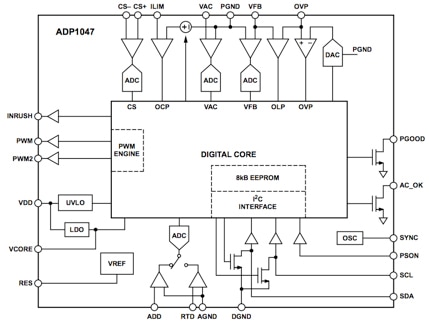
In some larger AC power supply subsystems a close-to-unity power factor (the ratio of real power flowing to the load to the apparent power in the circuit) is a requirement to improve power delivery efficiency. Power factor correction can be used to “shape” the current and voltage waveforms within the control subsystems to improve the overall power factor of the power subsystem. The methods for doing this are complex, but can be implemented in an MCU with sufficient processing power. An attractive alternative, however, is to use a dedicated external device that implements power-factor correction. The Analog Devices ADP1047 , shown in Figure 4 below, provides inrush current control using a conventional boost power-factor correction technique with multiplication of the output voltage feedback combined with the input current and voltage. This provides optimum harmonic correction and delivers an improved system power factor.

Figure 4: Analog Devices ADP1047 block diagram. (Courtesy of Analog Devices)
Several status outputs are available as external signals to quickly indicate when operation strays from nominal. All key parameters can also be reported and adjusted via the PMBus interface, making it easy to include the device in an MCU- based design. The ADP1047 also provides accurate rms measurement of input voltage, current, and power making it possible to add significant intelligence to the design. Using a dedicated device can increase the bill of materials needed, but the added capabilities, without the need to learn and implement an unfamiliar control algorithm can save months in development time—a key advantage for many projects.
Conclusion
The precise mix of on-chip MCU features and external devices is more an art than a science, but understanding that these trade-offs are at the heart of an efficient design is a good starting point. Make sure you stay up to date on new MCU features targeted at power supply designs as well as new external devices that add features and simplify software development for complex algorithms. Example code, reference designs, and development boards should all be included in any efficient power supply subsystem design.
For more information about the parts discussed in this article, use the links provided to access product pages on the DigiKey website.
References
免责声明:各个作者和/或论坛参与者在本网站发表的观点、看法和意见不代表 DigiKey 的观点、看法和意见,也不代表 DigiKey 官方政策。


 中国
中国