


Rapidly Build Mesh Connected Lighting Applications with Zigbee and Thread
投稿人:DigiKey 北美编辑
2018-04-11
For home, building, and industrial automation applications, connected lighting systems are convenient and can help save energy. While 802.15.4 based mesh networks provide an effective combination of low-power operation, extended range, and availability, they are complex to implement.
To reduce this complexity and save development time, silicon vendors have introduced reference designs and tools that can help designers quickly begin evaluating mesh connected lighting applications.
This article looks at the requirements for mesh networks in automation applications and describes the roles of Zigbee and Thread in meeting these requirements. The article then introduces a connected lighting kit from Silicon Laboratories as an example. It then proceeds to show how to use it to develop mesh connected lighting applications based on Zigbee or Thread protocols.
Connected lighting key part of IoT
With the emergence of cost-effective LED lights, connected lighting has earned a growing role in residential and commercial automation applications. Connected lights allow users to tailor their working environment to the color and intensity most suited to their work and personal preferences.
More advanced automation systems extend this basic functionality with location-based support by adding occupancy sensors, or simply taking the presence of an active LED light as an occupancy indicator. As with other applications in the Internet of Things (IoT), the associated data from these systems further provide their users with a variety of useful analytics.
Mesh networking
To help connect IoT devices such as smart LEDs, mesh communications protocols are rapidly emerging as a preferred solution, especially for low-power applications. With a conventional point-to-point network, a smart LED bulb on one side of a building would need to significantly boost its transmit output power to reach a controller on the other side of the building.
In a mesh network, a connected lighting device only needs sufficient transmit power to reach another nearby connected light device. In turn, individual devices in the mesh network route the source node’s message through the network until it reaches the destination node. As a result, mesh networks allow developers to employ low-power devices without sacrificing range.
In addition, the routing mechanisms built into a mesh network provide a self-healing capability. Messages are simply rerouted past failed nodes to maintain overall service availability.
For automation networks, Zigbee has become a popular choice among developers as it was designed from the start for low power consumption. Also, Zigbee Alliance certification ensures interoperability among different vendors. Zigbee networks can scale easily from a few devices to thousands. At the same time, an individual Zigbee device can provide the kind of short-range network typically found in home automation applications, and developers can deploy Zigbee mesh networks for longer range applications.
Development of these applications has also become more straightforward with the introduction of Zigbee 3.0, which reduces the clutter of separate application specific profiles into a generic application layer called the Zigbee Cluster Library (ZCL) (Figure 1).

Figure 1: Zigbee has emerged as a preferred solution for automation systems and provides developers with a set of powerful connectivity services collected in the Zigbee PRO stack and application specific services in the Zigbee Cluster Library (ZCL). (Image source: Zigbee Alliance)
The latest version of Zigbee provides improved features for mesh networking while maintaining compatibility with legacy systems. Still, Zigbee doesn’t yet natively support Internet protocol (IP) to connect with IP networks such as local Wi-Fi networks and the Internet.
To communicate between Zigbee and IP networks, developers need to adapt messages flowing through the gateway connecting each domain by translating headers and addresses between the respective network formats. In addition, developers typically need to repackage payloads and reapply security mechanisms. Although not conceptually difficult, this extra adaption process adds further processing burden to gateway devices with resulting increased message latency.
Lack of support for IP addressing in the baseline Zigbee specification has motivated developers to look for alternatives such as Thread from the Thread Group. As with Zigbee, Thread builds on the IEEE 802.15.4 physical (PHY) and media access control (MAC) layers. To provide IP addressability, it adds a layer of support for 6LowPAN (IPv6 over Low-Power Wireless Personal Area Networks). Thread also addresses other key mesh requirements with features such as up-to-date path information to speed rerouting and an enhanced protocol for securely commissioning a new device to a mesh network.
For developers, however, implementing applications such as connected lighting with these technologies presents multiple challenges in creating efficient hardware designs and optimizing applications on the associated software protocol stacks.
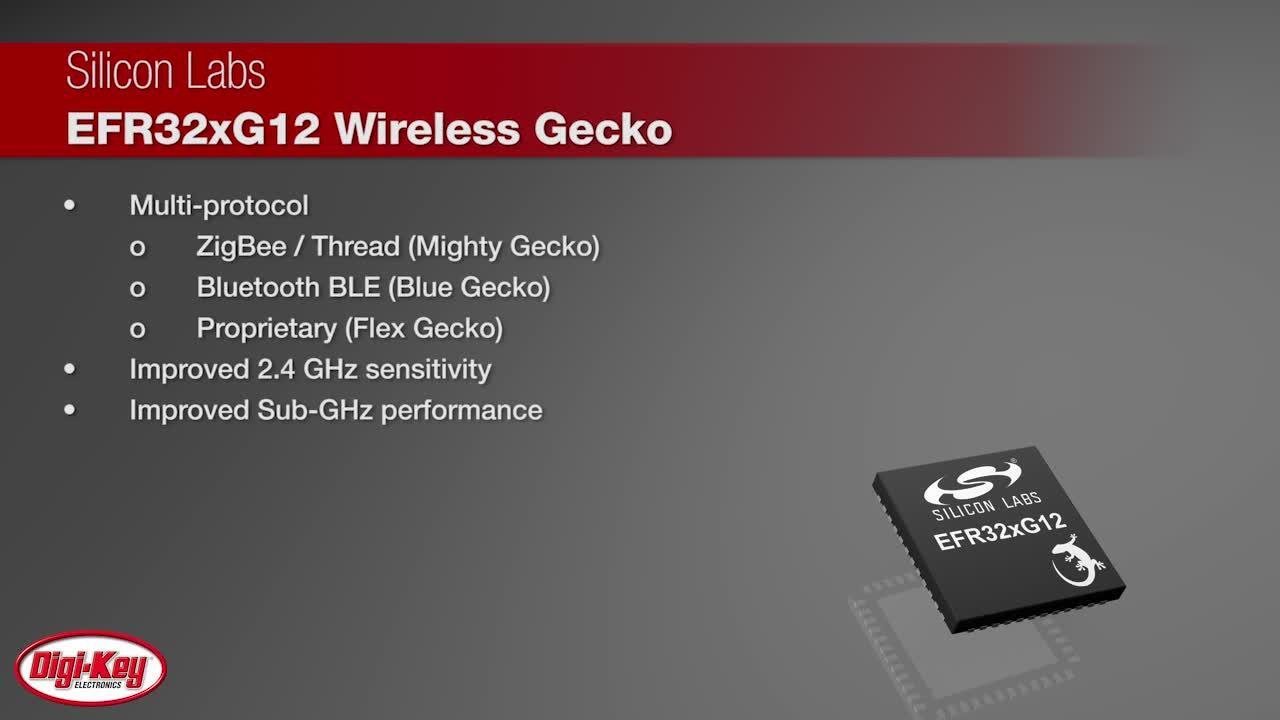
Using a Silicon Labs EFR32MG12 Mighty Gecko 802.15.4-enabled wireless MCU and associated software, developers can create low-power mesh networks. By building on a Silicon Labs reference design, developers can further accelerate their implementation of high level applications able to leverage those networks.
Wireless MCU
The availability of 802.15.4 enabled MCUs has accelerated the growth of automation applications built on low-power networks. Devices such as the EFR32MG12 MCU integrate a full complement of components required for a typical wireless node design. Along with their integrated radio, Mighty Gecko MCUs such as the EFR32MG12P432F1024GM48 combine a 40 MHz 32-bit Arm® Cortex®-M4 core with 1024 Kbytes of flash memory, 256 Kbytes of RAM, and an extensive set of digital and analog peripherals. The device’s analog interconnect matrix lets designers configure device pins as analog I/O ports for the integrated analog blocks, including digital-to-analog converters (DACs), analog comparators, op amps, and a high-speed 12-bit successive approximation register (SAR) analog-to-digital converter (ADC).
The device’s radio subsystem integrates full RF receive and transmit signal paths including a low-noise amplifier (LNA), a power amplifier (PA), a frequency synthesizer, signal converters, and a balun. As a result, designers can implement the RF side of a low-power design simply by connecting a two element LC matching network to the device’s two pin 2.4 GHz antenna interface (Figure 2). This two element design is sufficient for typical low-power IoT designs with modest RF transmit power requirements (less than 13 dBm). For designs with higher RF transmit power requirements, engineers only need to add another LC stage for a final four element matching network.

Figure 2: For 2.4 GHz 802.15.4 applications that require RF transmit power less than 13 dBm, engineers can implement the RF interface to an EFR32MG12 MCU with a simple two element LC matching network. (Image source: Silicon Labs)
Efficient IoT solution
Besides simplifying RF interface requirements, the MCU’s high level of integration simplifies overall system design. Developers can take advantage of an integrated DC-DC converter that requires only an additional external capacitor and inductor for deployment. As a result, the baseline design for an EFR32 based system requires few external components beyond those used for the power supply connections (Figure 3).

Figure 3: Developers can dramatically reduce power consumptions by using the EFR32 MCU’s built-in DC-DC converter to power internal circuit blocks, including the RF power amplifier for applications with low RF output power requirements. (Image source: Silicon Labs)
Designed to minimize noise that could affect the device’s RF circuits, the integrated DC-DC converter is nevertheless capable of delivering up to 200 mA to the MCU and other external devices through its IOVDD pin. Developers can also use the converter to supply the MCU’s internal blocks.
To power the I/O, RF analog and the RF PA stages, connect the converter output VDCDC to the chip’s respective pins (IOVDD, RFVDD and PAVDD). For applications with high RF output power requirements (above 13 dBm), simply move the high-side inductor connection shown in Figure 3 to the VDD supply.
Using the converter output for the internal digital and analog blocks is also straightforward, requiring a simple software setting. Developers can route the converter’s output to the MCU’s digital and analog blocks by respectively setting the REGPWRSEL bit and ANASW bit in the MCU’s EMU_PWRCTRL register.
Use of the integrated DC-DC converter brings distinct advantages not only in simplifying design but also in minimizing power consumption. In its EM0 active mode with peripherals disabled, the device consumes around 70 μA/MHz while running code from flash with a 38 MHz crystal. In contrast, power consumption rises to about 100 μA/MHz for designs running with the same operating conditions but without use of the integrated DC-DC converter.
Even so, the integrated DC-DC converter is only one of several features developers can use to reduce power consumption in an EFR32-based system. The device supports different operating modes that allow developers to scale voltage and clock frequency – reducing power at the cost of performance. Later, developers can simply scale up the voltage and frequency when the application requires higher performance before returning to the lower power state.
As with nearly all integrated MCUs designed for IoT designs, the MCU provides developers with multiple operating modes that can significantly reduce power consumption by placing the core and other subsystems in various sleep states. For example, the device requires only 41 microamps (µA)/megahertz (MHz) in sleep mode (EM1) with all peripherals disabled. During extended periods of inactivity, developers can drop power consumption to 3 µA in deep-sleep mode (EM2) or 2.47 µA in stop mode (EM3) with full RAM retention and internal flash powered down. To return to full active mode, it’s possible to program the device to automatically wake on interrupts from peripherals, or when the RF subsystem detects an RF signal.
For some designs, the time required for the MCU to wake from sleep can be a concern. Earlier generation MCUs exhibited slow wake-up times that could approach or even exceed the response time required by the application. With these devices, developers were forced to abandon the use of deep sleep modes, accepting higher power consumption to ensure a timely response from their systems.
In contrast, the EFR32 MCU wakes from EM3 stop mode in as little as 3 µs with code executing from RAM, or about 10 µs with code executing from flash. As a result, developers can take advantage of low power sleep modes without a significant impact on response time requirements for typical IoT applications such as connected lighting.
Connected lighting solution
Even with the EFR32 MCU’s simplified design requirements, developers can face significant challenges in creating a complete connected lighting application based on mesh networking. Besides the wireless MCU system, developers need to assemble LEDs and LED driving circuits with suitable buffers and interfaces for completing the connection to the MCU. Beyond these hardware design details, the software development requirements of a mesh connected application can be daunting.
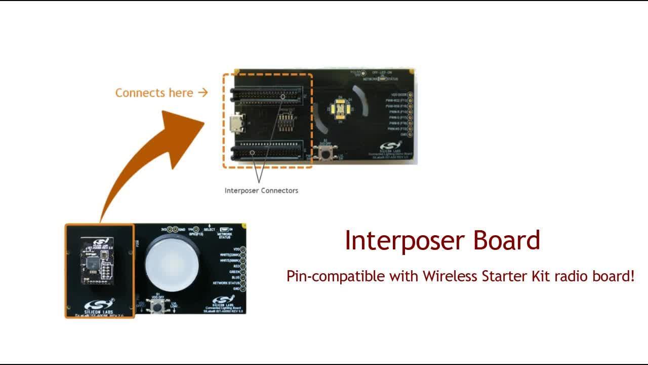
Rather than face delays in addressing these concerns, developers can use the Silicon Labs RD-0098-0401 reference design kit to quickly begin exploring connected lighting applications. Based on the Silicon Labs EFR32MG12P432F1024GM48 MCU mentioned earlier, the kit provides a complete system implementation including LED lighting features. The kit’s board comes with several LEDs with MOSFET driving circuits, and op amps to buffer the MCU pins used to control the MOSFET gates. Preloaded MCU firmware lets developers immediately begin examining different operating characteristics associated with the mesh network and the LEDs.
The associated reference design provides a clear roadmap for developing a wide range of automation applications based on mesh networks. By combining the RD-0098-0401 boards with the Silicon Labs SLWSTK6000B mesh kit and Simplicity Studio software environment, developers gain a comprehensive development framework for creating custom connected lighting systems (Figure 4).

Figure 4: The Silicon Labs RD-0098-0401 connected lighting kit works with the Silicon Labs SLWSTK6000B mesh kit and Zigbee gateways to provide a comprehensive platform for evaluating connected lighting and developing custom automation applications. (Image source: Silicon Labs)
As shown in the figure, developers can add any compatible Zigbee gateway such as Silicon Labs RD-0001-0201 Wi-Fi gateway or Silicon Labs RD-0002-0201 USB virtual gateway to connect compatible Zigbee devices in more complex automation applications. Perhaps the most critical piece of this development platform, the Simplicity Studio software environment, significantly improves application software development.
Development framework
In creating a Zigbee application, developers face specific functional requirements at each layer represented in the Zigbee architecture shown earlier in Figure 1. While 802.15.4 compatible hardware supports the lowest layers, developers are left with the task of ensuring that their software provides specific functionality expected by the other layers of the Zigbee architecture. Commercial Zigbee stacks such as the Silicon Labs EmberZNet protocol stack address the middle layers, but developers remain responsible for addressing further requirements at the application level (Figure 5).

Figure 5: The Silicon Labs stack provides a broad set of services required for Zigbee mesh networking, but developers remain responsible for complementary functionality at the application level. (Image source: Silicon Labs)
For software developers, working with the many dependencies and interactions across multiple layers in a rich framework like Zigbee can be extremely challenging. With Silicon Labs Ember application framework, however, they can instead focus more on their higher level application code rather than the underlying mechanisms.
Provided through Simplicity Studio, Silicon Labs’ Ember application framework simplifies Zigbee mesh development through a programming model built around callbacks. Callbacks provide a mechanism for application-level code to participate in operations handled at lower service levels, essentially providing an event-driven entry point into low-level mechanisms. At some point, typically just before or just after its critical processing sections, the lower service routine issues the callback, which is simply a call to a developer provided function that performs its own set of operations.
Callback programming models provide a number of benefits in complex frameworks. For example, the Ember framework uses callbacks to process new messages with the developer’s application-specific code, prior to execution of the lower-level service functions. In this way, callbacks not only provide a clean framework interface for the application developer, but also ensure isolation between the developer’s application code and the code provided with the framework. Silicon Labs expects that the framework is capable of handling any situation the developer might encounter, and considers it a framework bug if developers face a situation where they need to add application code to the framework.
Although the framework and its callback model already hide the complexity of the underlying service architecture, Simplicity Studio provides an even easier approach to application development. Here, developers can use the Ember AppBuilder within Simplicity Studio to build applications through a series of menu selections. Among these options, AppBuilder presents developers with a set of plugins that implement functionality of specific clusters such as color control supported in the standard Zigbee Cluster Library (ZCL) application layer.
Along with associated software modules, each plugin provides default values such as reporting interval as well as specific callbacks associated with that specific cluster’s functionality (Figure 6).
")
Figure 6: With the Silicon Labs Simplicity Studio AppBuilder, developers simply select the set of plugins (left panel) needed to implement application functionality including associated callbacks (lower right). (Image source: Silicon Labs)
The AppBuilder provides the complete source code needed to implement the underlying cluster functionality including specific callbacks. As illustrated in Listing 1, callbacks can range from a few simple lines of code to issue a stop command (emberAfColorControlClusterStopMoveStepCallback()), for example, to significantly more complex code needed to transition a target LED’s color from one state to another (emberAfColorControlClusterMoveToColorCallback()). After examining the default callbacks, developers can either implement their own versions of the callbacks or even create their own plugins.
Copy
bool emberAfColorControlClusterStopMoveStepCallback(void)
{
  // Received a stop command.  This is all we need to do.
  stopAllColorTransitions();

  emberAfSendImmediateDefaultResponse(EMBER_ZCL_STATUS_SUCCESS);
  return true;
}
   .
   .
   .
bool emberAfColorControlClusterMoveToColorCallback(uint16_t colorX,
                                                   uint16_t colorY,
                                                   uint16_t transitionTime)
{
  uint8_t endpoint = emberAfCurrentEndpoint();

  if (transitionTime == 0) {
    transitionTime++;
  }

  // New command.  Need to stop any active transitions.
  stopAllColorTransitions();

  // Handle color mode transition, if necessary.
  handleModeSwitch(endpoint, COLOR_MODE_CIE_XY);

  // now, kick off the state machine.
  colorXTransitionState.initialValue = readColorX(endpoint);
  colorXTransitionState.currentValue = readColorX(endpoint);
  colorXTransitionState.finalValue = colorX;
  colorXTransitionState.stepsRemaining = transitionTime;
  colorXTransitionState.stepsTotal = transitionTime;
  colorXTransitionState.endpoint = endpoint;
  colorXTransitionState.lowLimit  = MIN_CIE_XY_VALUE;
  colorXTransitionState.highLimit = MAX_CIE_XY_VALUE;

  colorYTransitionState.initialValue = readColorY(endpoint);
  colorYTransitionState.currentValue = readColorY(endpoint);
  colorYTransitionState.finalValue = colorY;
  colorYTransitionState.stepsRemaining = transitionTime;
  colorYTransitionState.stepsTotal = transitionTime;
  colorYTransitionState.endpoint = endpoint;
  colorYTransitionState.lowLimit  = MIN_CIE_XY_VALUE;
  colorYTransitionState.highLimit = MAX_CIE_XY_VALUE;

  writeRemainingTime(endpoint, transitionTime);

  // kick off the state machine:
  emberEventControlSetDelayMS(COLOR_XY_CONTROL, UPDATE_TIME_MS);

  emberAfSendImmediateDefaultResponse(EMBER_ZCL_STATUS_SUCCESS);
  return true;
}
Listing 1: Plugins provided with the Silicon Labs Simplicity Studio AppBuilder include specific callback functionality, which developers can replace as needed with their own callback functions or plugins. (Code source: Silicon Labs)
Migrating from Zigbee to Thread
With the Silicon Labs environment, developers can take advantage of a reasonably straightforward migration path from Zigbee to Thread. At the lowest level, Simplicity Studio generates hardware configuration output (hal-config.h) that can be used directly with stack software development kits (SDKs) for Zigbee, Thread, and even proprietary protocols using the Silicon Labs Radio Abstraction Interface Layer (RAIL) library with the Silicon Labs Flex SDK (Figure 7).

Figure 7: Along with using a common hardware configuration format, the Silicon Labs environment helps simplify migration of applications between different protocols including Zigbee and Thread. (Image source: Silicon Labs)
Silicon Labs’ Thread stack allows developers to migrate some higher level Zigbee application functionality to Thread as well. As part of its implementation of the Zigbee Alliance’s dotdot language for IoT connectivity, Silicon Labs used ZCL over IP (ZCL/IP) in implementing the Thread application layer included in its Thread stack. In supporting dotdot, ZCL/IP is intended to further generalize the functionality of application layers in the Zigbee architecture with different transport types. For its Thread stack, Silicon Labs takes advantage of this generality by providing an implementation of CoAP (Constrained Application Protocol) used as a standard transport protocol in Thread.
ZCL/IP maps a number of other Zigbee entities, commands, and attributes directly to the Thread IP network model. As a result, developers can more easily access the value of migrating to Thread. Even easier, developers can simply select a Thread implementation of the Silicon Labs RD-0098-0401 connected lighting demo in Simplicity Studio AppBuilder. As with the Zigbee demo, developers can immediately begin exploring Thread performance characteristics or use the AppBuilder generated sample application as the basis for their own Thread based automation applications.
Conclusion
LED lighting automation has rapidly emerged as a popular feature of smart homes and smart buildings. Underlying these automation systems, mesh networks support low-power operation of connected lights and control systems at ranges that once required high-power RF transceivers. In developing these mesh networking systems, however, developers face multiple challenges in implementing mesh capable hardware and software.
Used in combination, the Silicon Labs RD-0098-0401 connected lighting kit and Silicon Labs SLWSTK6000B mesh kit provide a complete hardware platform for creating mesh connected lighting systems. With Silicon Labs’ Simplicity Studio, developers can rapidly evaluate complete Zigbee and Thread based connected lighting applications, or use those sample applications for building custom mesh network automation applications.
免责声明:各个作者和/或论坛参与者在本网站发表的观点、看法和意见不代表 DigiKey 的观点、看法和意见,也不代表 DigiKey 官方政策。


 中国
中国