Power Supply Design Considerations for Mains Powered Equipment
投稿人:电子产品
2012-08-14
In a world where glamorous portable devices such as smartphones and tablet computers dominate the headlines, it easy to forget that most consumer electronic products draw power from the mains supply. And yet, these products use the same sensitive silicon – requiring stable, low-voltage power – as their handheld counterparts.
This article explains the basics of power regulation in mains-powered devices, from the line transformer that converts the high mains voltage to an isolated low voltage, through AC line rectification methods to convert the AC voltage to DC, and then to the DC/DC converter options that supply the stable low-voltage outputs required by the electronics.
The article includes a sample calculation to demonstrate how switching regulators are a more efficient solution than low-dropout (LDO) linear regulators for mains power supplies, leading to a more compact design that does not require heat sinks to remove excess heat.
Stepping down the mains voltage
Despite the fact that mains outlets around the world supply AC voltages from 90 to 264 V running at frequencies from 47 to 63 Hz, almost all office and home equipment cannot be plugged straight into a wall socket without some kind of power conversion.
The AC input typically has to be stepped down and the voltage regulated across a wide range of input line fluctuations and output loads. An additional challenge is to ensure that the DC output from the power supply does not include a significant AC component that manifests itself as voltage ripple. Most silicon circuitry requires a regulated supply that exhibits an output ripple of no more than one percent of the output voltage. What is more, just to make life a little more difficult, power supplies are typically required to deliver multiple output voltage and load capabilities. Figure 1 shows a simple schematic of a typical power supply for an item of office or home equipment.

Figure 1: This power supply converts AC mains voltage to three DC voltage outputs at three different output loads (Courtesy of National Semiconductor).
Mains supply voltage is high and dangerous to humans and electrical equipment alike; so the first requirement for a power supply is an isolating transformer. This rectifies the AC supply and steps the voltage down to a level that can safely be handled by a regulator.
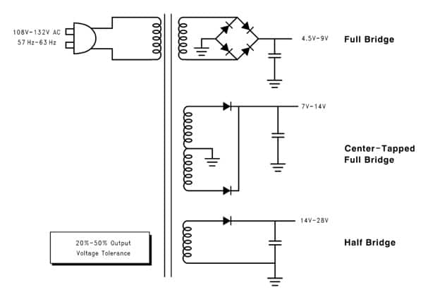
There are three common topologies for AC line rectification: full bridge, center-tapped full bridge, and half bridge. The full bridge is the most efficient technique, but requires four diodes in the design and consequently is a little more expensive. The center-tapped full bridge dispenses with two of the diodes, but requires more turns on the transformer’s secondary coil. The output ripple from each of the full-bridge rectification topologies is similar.
The half-bridge design is the least expensive, but does create a DC bias on the secondary winding so it is suitable only for low-current outputs. The voltage ripple is also larger than the full-bridge designs. Figure 2 shows the three different AC rectification techniques, and the voltage ranges they would produce from a 108 to 132-V supply.

Figure 2: AC line rectification methods (Courtesy of National Semiconductor).
While AC rectifiers can be used to step down a voltage, they are appalling regulators. In fact, even for a device using an ideal transformer, the regulation of the output will be no better than the input. So, for example, if the AC line variation is a typical ±10 percent, then the output voltage tolerance will be no better than ±10 percent.
The ideal transformer doesn’t exist, so the designer must take into account the resistance of the transformer windings. The effect of this resistance is to vary the output voltage according to the load. This effect is complex, and a definitive analysis can be found in a trusted old, but still applicable, reference work.¹ Nonetheless, taking all influences into account, the net load regulation for an AC rectifier can vary by between 10 and 40 percent. This degree of fluctuation is unacceptable for modern electronic components.
DC/DC conversion
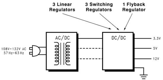
The output from an AC rectifier, although isolated from and of a much lower voltage than the mains supply, is not safe to apply directly to silicon components. The output from the rectifier has to pass through a further regulation stage to ensure a stable, relatively ripple-free output suitable for powering office or home equipment. There are three popular ways to do this: linear regulation, switching regulation, or flyback regulation.
The example shown in Figure 1 above requires three outputs from the AC rectifier, each linked to a linear regulator. Nonetheless, such a power supply is the easiest to design and would feature the lowest component count.
An alternative arrangement is to employ three step-down (“buck”) switching regulators. This design is likely to be more complex, but requires only a single output from the AC rectifier.
Another option is to use a flyback regulator. Figure 3 shows a schematic of a power supply using AC line rectification and linear, switching, or flyback regulation. This is a high-efficiency option, but it is even more complex than using switching regulators. Flyback regulators are suited to particular applications, particularly when a negative output is required, but would not be a good solution for the example discussed in this article. Consequently, further discussion will be limited to linear- and switching-regulator types.

Figure 3: Alternatives for regulation of AC rectified voltage (Courtesy of National Semiconductor).
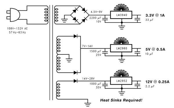
Figure 4 shows how linear regulators can be used to obtain the desired regulated output voltages when connected to the outputs of the AC rectifiers shown in Figure 2. (Note that the value of the bulk capacitors across the rectified transformer windings could be reduced depending on the transformer being used.) The linear regulators provide good rejection of the ripple voltage on the output of the transformer as long as the voltage does not go below the dropout voltage of the linear regulator.

Figure 4: Power supply using linear regulators. Relative inefficiency necessitates the use of heat sinks (Courtesy of National Semiconductor).
A key drawback of linear regulators is that they are not very efficient unless the difference between the input and output is small. Power is dissipated across a series resistor, generating excess heat that necessitates the use of heat sinks.
It's simple to calculate the power loss in the linear regulators from the formula:
PLOSS = VIN x IGND + (VIN −VOUT) x IL
Where VIN is the average DC voltage from the transformer, IGND is the ground-pin current at full load (see component data sheet), and IL is the output current.
In this example, calculations for power loss in the linear regulators assume a 132 V AC input to the transformer and full load on the outputs. This is the worst-case condition.
For the National Semiconductor LM3940 LDO linear regulator chosen for the 3.3-V output at 1 A DC, VIN is approximately 5.5 V DC, and the calculated power loss is 2.8 W (IGND = 110 mA).
For the LP2960 LDO linear regulator chosen for the 5.0-V output at 0.5 A DC, VIN is approximately 7.3 V DC, and the calculated power loss is 1.3 W (IGND = 21 mA, max).
For the LM2952 LDO regulator chosen for the 12 V output at 0.25 A DC, VIN is approximately 15.9 V DC, and the calculated power loss is 1.3 W (IGND = 21 mA, max).
Therefore, the total output power is 8.8 W and the total power loss is 5.4 W. Consequently, the line transformer must provide at least 14.2 W. If a lower-cost non-LDO were used, there would be an additional 3.8-W loss (because of the higher input voltage required, countered by lower supply current). This would result in a 27 percent increase in transformer size.
If a simple transformer with a single winding was used with LDO linear regulators, the extra loss would be 14.9 W, of which 12 W would be the loss in the 3.3-V regulator, dropping the voltage down from a 14-V winding.
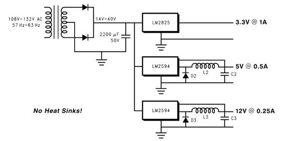
An alternative to the relatively inefficient LDO linear regulators is to use switching devices. Figure 5 shows what such an arrangement would look like.

Figure 5: Power supply using linear regulators is more efficient and can use a smaller and less complex transformer.
This solution uses three switching regulators, National Semiconductor’s LM2825 and LM2594 models. In this case, the three forms of AC rectification from Figure 4 have been replaced by a single transformer supplying between 14 and 40 V. Again, the size of the input capacitor may be reduced and the ripple rejection is good.
The overall efficiency of this switching regulator solution is approximately 80 percent. Therefore, the line transformer needs to provide only 11 W instead of the 14.2 W used in the linear regulator example. Because the power requirement is lowered, the transformer used in this solution can be 22 percent smaller than that used in the linear regulator solution. And because only one output winding is required, the transformer manufacture is simplified.²
Mains-powered equipment requires AC rectification and DC/DC regulation to supply stable, low voltages to delicate electronic components. Linear and switching regulators are both options for the DC/DC conversion. Power supplies using linear regulators are simpler, but designs using switching regulators offer greater efficiency.
References:
- “Analysis of Rectifier Operation,” O H Shade, Proceedings of the Institute of Radio Engineers, July 1943.
- “Application Note 1061 Power Conversion in Line-Powered Equipment,” Texas Instruments, 2002.
免责声明:各个作者和/或论坛参与者在本网站发表的观点、看法和意见不代表 DigiKey 的观点、看法和意见,也不代表 DigiKey 官方政策。


 中国
中国