Power Control for LED Lighting
投稿人:DigiKey 欧洲编辑
2016-02-25
Smart lighting is one of the keys to the smart home. Radio and network control can be used to alter the level of lighting either by direct control from the user, employing a dedicated remote control or with the help of a smartphone app, or automatically based on time of day. However, LED power control for lighting requires special consideration. Circuitry developed for traditional dimming control does not work well with the requirements of solid-state lighting.
Most dimmers installed in homes are based on a phase-cut circuit. The advantage of this type of circuit is that it is very simple to design and is robust. The circuit works by simply cutting the supply to the bulb for a portion of the AC cycle, reducing the overall voltage supplied to the filament. This, in turn reduces the filament’s light output. Because of the comparatively long time that it takes for the filament to heat up and cool down, this switching is not noticeable to the user except possibly at the very lowest settings of the dimmer.
However, with LEDs, which have much shorter response times, the low switching frequency of the main supply means that attempting to use a similar strategy to control the light output will result in significant flickering. As a result, LEDs require specialized power supply circuits that can deliver a more consistent voltage and current output to provide power that minimizes flicker without compromising efficiency.
Although it is possible to manipulate light levels from LEDs by altering the current supplied to them, this results in a drop in power efficiency at lower current levels. A power LED provides its best efficiency at the highest rated current. So, dimming behavior is still best obtained using pulse-width modulation (PWM) techniques, turning the LED on and off at higher frequencies than would be supported by traditional mains-based dimmer circuits.
In a PWM-based power converter, a reference signal fed back to the controller is used to determine whether the transistor that feeds power to the load should be on or off. The reference is compared to a periodic signal created by a ramp generator. While the reference signal is higher than the ramp, the transistor is switched on. When the reference signal falls below the ramp, the transistor is switched off. The integrated current delivered therefore follows the profile of the reference signal. Various techniques can be used to control the reference signal and therefore manipulate the power output. For smart-home use, power converters can integrate additional inputs that tune the reference signal based on the preferred dimming level.
The power converters for LEDs may also be designed to handle different supply types. For example, a simple retrofit bulb that includes the LED ballast, dimming control and RF interface to a smart-home network, will generally work with a 50 Hz/60 Hz mains supply. However, the power converters for bulbs that are designed to go into low-voltage strips and buses will need to be able to handle DC supply inputs instead.
Inrush current is an important consideration in LED lighting design. The power supply to the LED presents a capacitive load to the mains supply, which leads to the potential for a high current to be drawn for a short period when the LED is switched on as the capacitors around the supply charge. Because this current can be much higher than the steady-state current, it can lead to overload problems when a large number of lamps attached to one mains circuit are activated. Limiting inrush current at startup provides a design that has greater compatibility with home electrical circuits.
Power-factor correction (PFC) is a further consideration in terms of mains compatibility. The switched-mode techniques needed for efficient LED dimming should not be allowed to drive additional harmonics onto the electricity supply.
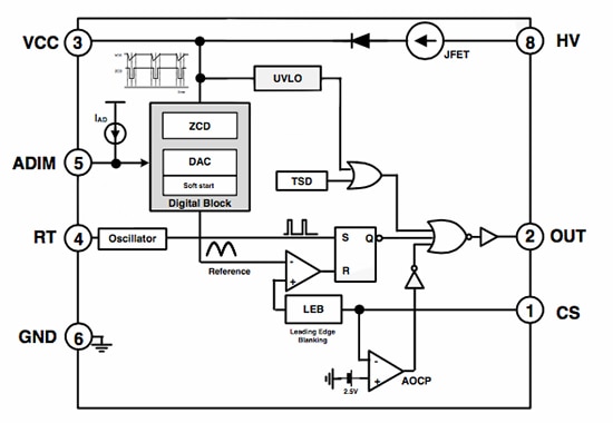
The need for efficient power delivery and support for PFC has led to the introduction of parts such as the Fairchild FL7701. The Fairchild FL7701 has been designed to work with both AC and DC supplies, using the ripple voltage transmitted to its low-voltage VCC pin from the high-voltage supply as a means of detection. The ripple on the VCC rail is used using a sigma-delta modulation scheme to provide a reference signal to the PWM switching circuitry. When a DC input is applied, the lack of ripple on the VCC rail results in a reference signal suitable for DC-mode power conversion without PFC.

Figure 1: Block diagram of the FL7701.
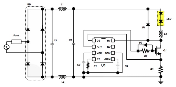
To support remote control, the FL7701 has an analog input pin that can support 0 V to 10 V dimming control by using a resistive divider. This signal is fed into the digital controller and used to determine the output of a digital-to-analog converter that provides the reference signal to the PWM control circuitry. A microcontroller can be used to generate the input signal to the LED ballast, potentially receiving its commands from an RF interface.

Figure 2: The FL7701 in a typical application.
The FL7701 employs a soft-start function to limit inrush current, applying a delay to the internal voltage reference signal used by the PWM circuitry so that it rises slowly from initial startup. A similar soft-start feature is available on the SSL4101T Greenchip III+ from NXP. On this device, the soft-start period is determined through selection of an external resistor and capacitor.
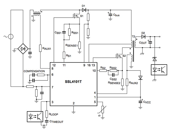
Able to work with conventional triac dimming techniques, and so support systems that need to handle a mixture of lighting sources, the SSL4101T was designed to provide high efficiency at all power levels; using a variety of PWM control techniques to suit the conversion to the desired output light level. The device moves from quasi-resonant operation at high power levels to quasi-resonant operation with valley skipping through to reduced-frequency operation at low power-output levels, reducing the current supplied to the LED to avoid generating audible noise from the ballast’s transformer.

Figure 3: Block diagram of the SSL4101.
In quasi-resonant mode, the next converter stroke is started after demagnetization of the transformer that should be provided as part of the front-end circuitry to the SSL4101T. This helps to minimize losses, as the converter only switches on when the voltage across the external MOSFET is at its minimum. To reduce the frequency of operation at lower loads, the quasi-resonant operation changes to discontinuous mode operation with valley skipping in which the switching frequency is limited for EMI reasons, typically to around 125 kHz. Again, the external MOSFET is only switched on when the voltage across the MOSFET is at its minimum.
At very low-power and standby levels, the frequency, which can be reduced to almost zero, is controlled down by a voltage-controlled oscillator (VCO). During frequency reduction mode, the primary peak current is kept at a minimal level of 25 percent of the maximum. In frequency reduction mode the PFC controller is switched off as the harmonics generated will be minimal. To prevent oscillation around the PFC-operation point, the device supports approximately 50 mV of hysteresis on the control pin.
The ability of the SSL4101T to support very-low input power in standby mode eliminates the need for an additional housekeeping power supply to power the lighting controllers or dimmers.
Although design for LED smart lighting involves more complex power conversion than dimming control for incandescent lamps, integrated devices such as the FL7701 and SSL4101T can ease the design burden and achieve high efficiency.

免责声明:各个作者和/或论坛参与者在本网站发表的观点、看法和意见不代表 DigiKey 的观点、看法和意见,也不代表 DigiKey 官方政策。


