No-Opto Flyback Topology Simplifies Isolated DC/DC Converter Design
投稿人:电子产品
2013-09-17
Besides being used in telecom and datacom systems, isolated DC outputs are also required in many other noise sensitive applications such as car battery charging, intermediate bus voltages for a variety of electronic loads, and industrial inputs. While a flyback topology is popular for isolated DC/DC converter applications, because of its relative simplicity and low cost compared to alternative isolated topologies, designing a traditional flyback is not easy as the transformer requires careful design, and loop compensation can be complex. In addition, it requires an opto-coupler or extra transformer winding for feeding back the output voltage from the secondary side to maintain output accuracy.
Propagation delay, aging, and gain variation of the opto-coupler further complicate loop compensation and the stability of the flyback converter, while limiting the transient response of the converter. In addition, opto-couplers consume power and increase the cost and physical size of the power supply. Designing a high-performance transformer with extra winding can take a significant amount of time as there is a limited selection of off-the-shelf transformers. Finally, using an extra winding adds to the transformer’s physical size and cost.
Fortunately, recent advances in power conversion technology have made low-power isolated converters much easier to design. By incorporating a primary-side sensing scheme and running the converter in boundary mode, Linear Technology’s no-opto flyback converters, such as the LT3574 and LT8300, simplify the design of flyback converters by eliminating the need for an opto-coupler, external MOSFET, secondary-side reference voltage, and extra transformer winding. Its boundary mode, which is a variable-frequency, current-mode, control switching scheme (more on this shortly), also results in improved regulation over the full line, load, and temperature ranges. According to Linear, boundary mode also permits the use of a smaller transformer compared to equivalent continuous conduction mode (CCM) designs. These flyback solutions are popular in isolated power supplies ranging from less than a watt to tens of watts.
Primary-side sensing
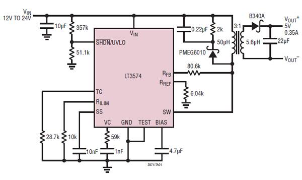
Designed specifically for the isolated flyback architecture, the monolithic LT3574 operates with input supply voltages from 3 V to 40 V, and can deliver output power up to 3 W with no external power switch because it integrates on-chip a 0.65 A, 60 V NPN power transistor. The output voltage is easily set with two external resistors connected to the RFB and RREF pins, and the transformer turns ratio as shown in Fig.1.

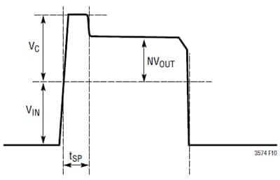
As per the description in LT3574’s datasheet, the output voltage is accurately measured at the primary-side switching node waveform during the off time of the power transistor (Fig. 2), where N is the turns ratio of the transformer, VIN is the input voltage, and VC is the maximum clamped voltage. The flyback converter turns on its internal switch immediately after the secondary-side current reduces to zero and turns off when the switch current reaches the pre-defined current limit. Therefore, the device always operates at the transition of continuous conduction mode (CCM) and discontinuous conduction mode (DCM), commonly referred to as boundary mode or critical conduction mode.

Linear’s explanation shows that the boundary mode control is a variable-frequency, current mode switching scheme. When the internal power switch turns on, the transformer current increases until its preset current limit set point is reached. The voltage on the SW pin rises to the output voltage divided by the secondary-to-primary transformer turns ratio plus the input voltage. When the secondary current through the diode falls to zero, the SW pin voltage falls below VIN. The internal DCM comparator detects this event and turns the switch back on, repeating the cycle.
Boundary mode returns the secondary current to zero at the end of every cycle, resulting in the parasitic resistive voltage drop not causing load regulation errors. Furthermore, the primary flyback switch is always turned on at zero current and the output diode has no reverse-recovery loss. This reduction in power loss allows the flyback converter to operate at a relatively high switching frequency, which in turn reduces the transformer size when compared to lower-frequency alternative designs.
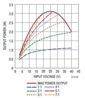
Figure 3 shows the measured output power for a 5 V flyback converter using LT3574. The data sheet shows that with a 3:1 transformer winding ratio this design example provides output power close to 2.5 W at 30 V input voltage and about 2 W at 20 V input.

The transformer specification and design is probably the most critical part of successfully applying the LT3574. Since the voltage on the secondary side of the transformer is inferred by that of the primary side, the turns ratio must be tightly controlled to ensure a consistent output voltage. Linear Technology has worked with leading magnetic component manufacturers to produce pre-designed flyback transformers for use with the LT3574. A number of off-the-shelf transformers for a variety of output voltages and current levels from Würth Elektronik and other suppliers are listed in a table in the LT3574 data sheet. According to Linear, the transformer turns ratio is selected such that the converter has adequate current capability and a switch stress below 50 V. Table 1 shows the switch voltage stress and output current capability at different transformer turns ratio.
| N | VSW(MAX) at VIN(MAX) | IOUT(MAX) at VIN(MIN) | Duty Cycle |
| 1:1 | 33.5 V | 0.34 A | 16% ~ 22% |
| 2:1 | 39 V | 0.57 A | 28% ~ 35% |
| 3:1 | 44.5 V | 0.73 A | 37% ~ 45% |
| 4:1 | 50 V | 0.84 A | 44% ~ 52% |
Table 1: Switch voltage stress and output current capability versus turns ratio.
To simplify the task of selecting the right transformer from the parts listed in the datasheet table, the LT3574-based DC/DC flyback converter can be modeled using any of the transformers listed. By downloading a free copy of the LTspice simulation software from the company website, designers can simulate and produce realistic results to confirm the transformer and the design of flyback converters, Linear says. The simulation circuit includes information on how the circuit starts up and its reaction to load steps for different input voltages. According to Linear, it is easy to make changes and see the impact on the converter’s performance.
High input voltage
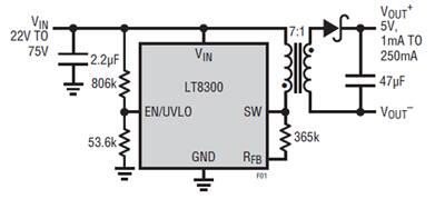
For applications such as telecom, automotive, industrial, and medical systems, where input voltage can be as high as 100 V, Linear is offering its LT8300. To simplify the isolated flyback converter solution, LT8300 integrates a 260 mA, 150 V DMOS power switch, an internal compensation network, a soft-start capacitor, and all control logic functions. As a result, using only a handful of external components, the part can deliver up to 2 W of isolated output power at 5 V (Fig. 4). The input supply voltage range for this converter is 6 V to 100 V.

As shown in Fig. 4, the isolated output voltage can be set via a single external resistor with compensation and soft-start circuitry integrated in the converter chip. Low ripple-burst mode operation maintains high efficiency at light loads while minimizing the output voltage ripple.¹
Using a few external components, Linear’s no-opto flyback converter chips simplify the design of low-power isolated DC/DC converters with high efficiency and tight regulation. In addition, they can operate over a wide input voltage range with input as high as 100 V.
For more information on the parts discussed in this article, use the links provided to access product pages on the DigiKey website.
Reference
- Design Note 509, “Micropower Isolated Flyback Converter with Input Voltage Range from 6 V to 100 V” by Zhongming Ye, Linear Technology Corp.
免责声明:各个作者和/或论坛参与者在本网站发表的观点、看法和意见不代表 DigiKey 的观点、看法和意见,也不代表 DigiKey 官方政策。


 中国
中国