New Components, Approaches Solve Low-Voltage Circuit-Protection Challenges
投稿人:DigiKey 北美编辑
2016-04-14
Circuit protection is one of those thankless design considerations: it's an insurance-like cost that is little appreciated when things are going well; when there's a problem, it's expected to provide full protection against anticipated and even hard-to-anticipate events. Designers need to provide circuit protection that is matched to the demands of the application, against any internal and external events, which may adversely affect system reliability or even induce outright failure. Depending on the application and system topology, protection may be needed at one or more or points including individual components, at the interconnection between internal stages, and at the system external signal and power interfaces.
There are many long-standing, time-tested, customary ways to implement protection, and there are also new, innovative approaches and components designed for some specific, increasingly common protection situations. The first challenge for engineers is to understand what they need to protect against. Among the concerns are:
- Overvoltage (both steady state and transient)
- Overcurrent, either just exceeding a modest guard-band threshold or as a complete short circuit (again, both steady state and transient)
- Thermal extremes (usually overtemperature, but cold may also be a consideration)
- Reverse-battery connection (most often associated with autos)
- RFI/EMI-induced transients
Some of these protection concerns are due to an internal failure such as when a power device fails and develops a short circuit; others are due to external events such as accidental shorting of the output of a power supply to ground or a terminal of a component to the power rail; while others are the result of large-scale external issue such as lightning hitting the device directly or nearby. Further, some faults, such as shorting a power-supply's output, may be steady state, while some are transient events, such as those induced by EMI/RFI (although the failure they induce may be long lasting, of course).
In most cases, it's neither practical nor necessary to protect every product against all possible failure modes. For example, there is no need to protect a consumer-grade smartphone from a direct lightning strike, while there is a need to do so for aircraft electronics. Also, the range of "excessive" can be quite wide: for a handheld, battery-powered device, overvoltage on some internal circuitry may be below 10 V, while for a power supply it may be tens or hundreds of volts.
To meet the diverse needs of these systems, vendors have developed a wide array of circuit-protection devices along with topologies, which make best use of these devices. Among the many protection devices available are:
- Basic semiconductor diodes, including Zener and Schottky diodes
- Active "ideal" diodes
- Basic meltable-link fuses
- Circuit breakers
- Varistors (also called a MOV, or metal-oxide varistor)—"breaks down" and shorts above voltage threshold, then self-resets
- Positive temperature coefficient device (PTC)—resistance increases sharply above a current threshold, then self-resets
- Transient-voltage suppressors (TVS)—action is like a varistor, though voltages and speed are different
- Gas discharge tubes (GDT)—action is like a varistor, though voltages and speed are different
In some cases, the role of the circuit-protection device is to protect the entire system, while in other cases it is to "save" a specific high-value component (such as a power MOSFET or IGBT) from damage if there is an external problem.
In addition to their different ratings and basic capabilities, there are key differences among these protection devices:
- Most of these are passive (such as diodes), but some are active devices with advanced features.
- Some (such as TVS devices), are fast and act within milliseconds or even microseconds, while others are slower acting and can take several seconds to react (meltable-link fuses), which may be acceptable and even desirable in their application.
- A few are one-time-use only and must be manually replaced or reset after they perform their protection function (fuses with meltable links or circuit breakers), while many are self-resetting (GDT); the trend is to use the latter whenever possible and acceptable.
New devices supplement, improve upon existing solutions.
There's a long-standing pair of automobile-related situations, which now have increasingly severe consequences: reverse-battery connection and load dump. The former can occur when someone incorrectly connects the plus (+) and minus (-) cables to the battery in the car. Several decades ago, when cars had no electronics except for the radio and even the dashboard was mostly mechanical, the damage from this would be minimal, if at all. The same concerns apply to the load-dump transient that occurs when the car is shut off and any stored energy in the electrical system and circuitry suddenly discharges.
However, either one of these occurrences can have severe consequences in today's cars, which are packed with sophisticated electronics including ADAS (advanced driver assistance systems) including backup camera, navigation, anti-lock braking system (ABS), and anti-rollover sensing; high-end entertainment systems; GPS; wireless connectivity; and internal networks including Ethernet. A reverse-connected battery or load dump could easily cause major, dangerous, and expensive failures across many of these subsystems, especially as the car battery can easily deliver several hundred amps to the load.
The traditional solution to reverse-voltage protection is to use a passive semiconductor diode to protect each subsystem or circuit function (Figure 1). While this works, the approach has several disadvantages. The major one is due to the diode's forward voltage drop, between 0.3 and 0.8 V depending on diode type. This brings two problems: in low-voltage systems such the car and its nominal 12 V battery, even that small voltage loss can be a large part of the available rail potential; further, given the high current being drawn from the battery, the drop translates to power loss, inefficiency, and even excessive thermal dissipation which may cause the diode to fail. The math is simple: using a low-drop 0.3 V Schottky diode, the dissipation of a modest 10 A load is 30 W.

Figure 1: The traditional way to prevent against the effect of reverse battery and load dumps is to use a diode in series in the supply rail, but this has serious deficiencies in terms of voltage drop and power dissipation. (Source: Texas Instruments)
Fortunately, active devices with clever topologies provide an alternative. The recently introduced LM74610-Q1 Smart Diode Controller from Texas Instruments is a two-terminal device like a diode, with an anode and cathode, with an integrated charge pump to provide gate drive to an associated NFET device. Under normal operating conditions, the transistor is turned on and so there is very low dissipation; also, there is zero quiescent current as there is no conduction path to ground (Figure 2).

Figure 2: The LM74610-Q1 Smart Diode Controller from Texas Instruments implements a fast-acting, near-ideal diode with no dissipation, and solves the reverse battery/load dump dilemma. It is placed on each circuit board in the system that has a power rail which may be adversely affected. (Source: Texas Instruments)
The LM74610-Q1 features a response time of less than 8 μsec when voltage is reversed, important for protecting against load-dump transients, and can tolerate reverse voltages up to 45 V maximum, exceeding the automotive required overvoltage range. The tiny 8-lead, 3 mm × 5 mm VSSOP-8 package has minimum footprint impact on the various circuit boards within the car, which is also a benefit.
Shorter transients also a problem
It's not just issues with the power rail that designers must anticipate. Short-duration, high-energy overvoltage events caused by ESD (electrostatic discharge), CDE (cable discharge events), and EFT (electrical fast transients) can disrupt or damage sensitive components which are connected to high-speed data and transmission lines, even in consumer applications such as USB interfaces.
To avoid these problems, basic transient voltage suppressors (TVSs) are used. TVS devices must not only clamp the overvoltage event, but they must do so quickly. They also must have very little capacitance so they do not distort the data signal, stretching the slew times of the leading/falling edges of the data signal and thus impeding normal high-speed performance.
For example, the RClamp®1521PQ family from Semtech Corp. has a maximum capacitance of only 0.5 pF, so it can be used on high-speed links with bandwidths up to 3 GHz. Each device consists of a two reverse-connected diodes in series, and can protect a single data line operating at up to 15 V as a result of its nominal breakdown voltage of 20 V at 50˚C (Figure 3). When the applied voltage exceeds the design threshold, one of the diodes goes into reverse-breakdown mode and clamps the excessive voltage. These single-function, easy-to-use components meet the ESD immunity requirements of IEC 61000-4-2, Level 4 (±15 kV air, ±8 kV contact discharge).

Figure 3: The concept of the basic TVS is simple: use a pair of back-to-back diodes; when the reverse breakdown voltage of either is exceeded by a positive or negative voltage, the corresponding diode will go into breakdown mode and clamp the excessive applied voltage. (Source: Semtech Corp.)
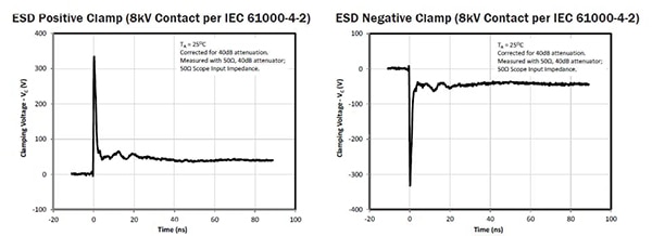
The devices are single-channel, two-pin and come housed in 1.0 × 0.6 × 0.5 mm packages with a lead pitch of 0.65 mm for minimal footprint; larger, multi-channel array versions are also available for groupings of data lines. The response time of these TVS units is fast, on the order of a few nanoseconds for both positive and negative transient events (Figure 4).
Figure 4: TVS devices in the RClamp®1521PQ family from Semtech show nanosecond-range response to positive and negative spikes, clamping the offending voltage before any damage can occur. (Source: Semtech Corp.) Click here to view the full-size image.
Low voltage gets attention, but higher voltages get increased roles
In a world where single-digit voltage operation gets most of the attention, it’s important to note that higher-voltage designs in the tens of volts are still vital, especially where higher power levels are involved. For this and other reasons, MOV vendors are introducing higher-voltage versions of their lower-voltage product families.
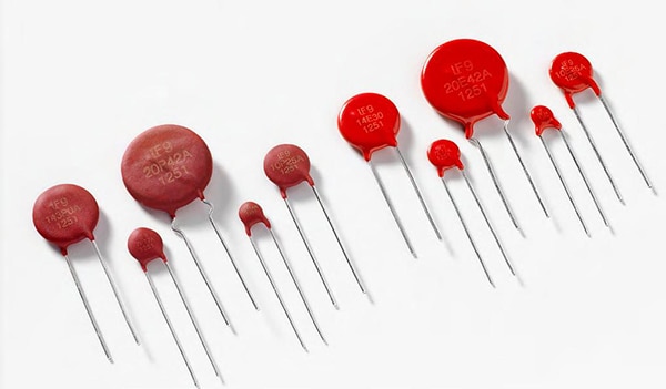
Littelfuse, Inc. recently expanded its LV UltraMOV™ Varistor Series, covering the 14 VDC to 56 VDC range (with surge-current rating of up to 8 kA with a 8/20 μs pulse) to handle continuous voltage ratings from 65 VDC to 125 VDC, and with an enhanced surge-current rating of up to 10 kA (8/20 μs pulse).
These disk-shaped devices (Figure 5) with diameters of 5, 7, 10, 14 and 20 mm target telecom power systems, wireless base stations, automation controls, audio and video devices, security systems, and fire-alarm systems applications. The phenolic coating option supports higher operating temperatures up to 125°C, compared the standard epoxy coating rating of 85°C, but otherwise has nearly identical specifications.

Figure 5: The disk-shaped LV UltraMOV™ Varistor Series from Littelfuse, Inc. supports a wide range of maximum clamping voltages (a function of MOV diameter) and currents. (Source: Littelfuse, Inc.)
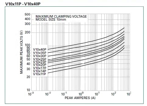
Maximum clamping voltage is a function of the MOV diameter, and Figure 6 shows that voltage versus peak current for the 10 mm family, where clamping voltage on the graph curve is indicated by the last two digits (XX) of the suffix "XXP". The maximum peak-surge current can reach up to 10 kA, a peak that can be induced by indirect lightning strikes or system switching.

Figure 6: The maximum peak voltage versus peak current, here for the 10 mm family, shown for clamping voltages between 11 and 40 V; note that the current can reach into the kA range. (Source: Littelfuse, Inc.)
Conclusion
The often under-appreciated task of implementing circuit protection encompasses a wide range of potential conditions related to current, voltage, and temperature, and can be the result of internal or external events and exist as transient or steady-state occurrences. To provide the proper protection, designers must first define the type and intensity of the potential problems, and then select one or more circuit-protection components and related techniques.
Some of these have been in the engineers "toolkit" for many years, but there are also new devices which extend the range of older ones, or which provide new and innovative active solutions and topologies. These newer devices have a large role in meeting the challenges of today's systems, which span an increasingly wide range of requirements in size, power, speed, and cost.

免责声明:各个作者和/或论坛参与者在本网站发表的观点、看法和意见不代表 DigiKey 的观点、看法和意见,也不代表 DigiKey 官方政策。


 中国
中国