Multi-output, Multi-phase Voltage Regulator Modules Tackle Demanding Applications
投稿人:电子产品
2012-01-03
Standard circuit-board-mountable power conversion modules are still a mainstay for many system designers. Such modules provide DC/DC conversion with anywhere from one to six voltage outputs and current levels ranging from a few milliamps to several amps. The module output voltages are usually factory-set at typical operating levels such as 3.3 V, 5 V, 12 V, or even lower voltages. Many vendors, though, do offer versions that allow the customer to set the desired output voltage via an externally connected resistor. Industrial equipment, networking systems, telecommunications hardware, and even consumer products such as set-top boxes can all leverage such predesigned modules to gain some time-to-market advantage and not distract the system design from delivering their “value added” features to the end system.
There are a wide variety of DC/DC voltage regulator modules (VRMs) available and designers have a choice of many voltage input and output levels, multiple outputs, current ratings, and physical size. Packaging options range from through-hole mounting to various surface-mount choices such as multi-pin, dual-in-line flat packages, quad-sided flat packages with as few as 10 pins, to larger land-grid arrays with up to 144 contacts (many of those contacts are used to provide a thermal path, thus minimizing the need for a large heat sink).
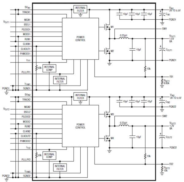
One example is the LTM4616 from Linear Technology. In a single 144-contact LGA that measures 15 x 15 mm and is only 2.82 mm thick, the company packs the switching controller, power FETs, inductor and all support components (Figure 1). Operating from an input voltage range of 2.7 to 5.5 V, the LTM4616 µModule supports two outputs within a voltage range of 0.6 to 5 V, each set by a single external resistor. This high efficiency design (typically 85 to 93 percent, depending on load current) delivers up to 8 A continuous current (10 A peak) for each output. Only bulk input and output capacitors are needed, depending on ripple requirement. The part can also be configured for a two-phase single output at up to 16 A. The low-profile package enables designs to use the unused space on the back side of PC boards for high-density point-of-load regulation. Fault protection features include overvoltage protection, overcurrent protection and thermal shutdown.

Figure 1: The LTM4616 uModule from Linear Technology is a complete DC/DC converter and regulation system in an ultrathin land-grid-array package.
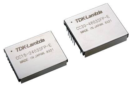
When space is not that much of a concern, DC/DC converters in shielded 2 in. x 1.5 in modules, such as the PXE series DC/DC-converters from TDK-Lambda provide point-of-load power of 20 W for the PXE20 series and 30 W for the PXE30 series. The converters have a preset voltage accuracy of ±2 percent for the PXE20 family and ±1 percent for the PXE30 family. These devices are part of the company’s larger PX Series which includes versions with power ratings ranging from 15 to 60 W. Another family of converters from TDK-Lambda, the CC-P-E (Figure 2) modules offers efficiencies of up to 92 percent, typical, and output power ratings of 15 or 30 W. These converters are available in either through-hole or surface-mount package options.

Figure 2: With shielding on all six sides, these DC/DC converter modules in the CC-P-E series from TDK-Lambda use through-hole mounting on the circuit board and deliver 20 W (left) and 30 W (right).
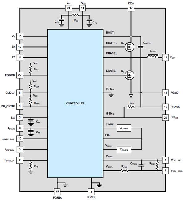
The ISL8200M from Intersil demonstrates yet another form factor popular for the board mountable VRMs (Figure 3). Housed in a 15 x 15 mm thermally-enhanced, compact QFN package that is only 2.2 mm thick, the ISL8200 operates at full load and over temperature without requiring forced air cooling. It is even thinner than the module from Linear Technology and it too can fit on the backside of the PCB, thus saving space on the main side of the circuit board. A complete switch-mode power supply in one package, the ISL8200 has a maximum current output of 10 A, but multiple units can be paralleled (up to six) thanks to a patented current-share architecture that reduces layout sensitivity when the modules are paralleled. A single resistor sets the output voltage over a 0.6 to 6 V range.

Figure 3: At just 2.2 mm thick, the ISL8200 VRM module from Intersil uses a thermally enhanced 15 x 15 mm QFN package to present a small form factor that can deliver up to 10 A without forced-air cooling.
Many of today’s high-performance systems incorporate power-hungry chips on the circuit boards, and those chips often require dedicated voltage-regulator modules that deliver precise voltages that can be dynamically controlled. For example, high-performance microprocessors, field-programmable logic arrays, and many application-specific ICs have power consumptions in the 40 to 140 W range and operate at supply voltages of less than 1.3 V for their core logic and 2.5 or 3.3 V for their I/O pins.
Such localized high-power requirements have created a new class of point-of-load multiphase voltage regulator module (MVRM) that incorporates a digital control port. The control port feeds data into a 5-bit, digital-to-analog converter (DAC) in the module that controls the final output voltage. The multi-bit input to the DAC often comes from the chip the MVRM is trying to power. High-performance microprocessors are good examples of such chips. The processors are typically programmed to specify their optimum operating voltages during the processor vendor’s test process. Intel defined the original concept for the VRMs for its processors, and other companies have leveraged that concept.
When powered up, the processor chip sends the setting to the MVRM, which adjusts its output level to match the optimal value set by the programmed chip. This on-the-fly ability to change the operating voltage can also be leveraged by power management software to lower or raise the supply voltage depending on the task the processor is executing. The MVRM reads the multi-bit setting from the voltage ID (VID) pins on the chip that it is powering and those bits control the setting of a digital-to-analog converter in the MVRM. The DAC, in turn, provides a fine-tuning adjustment to the output voltage.
Today’s high-performance logic circuits are designed to operate from low-voltage power supplies of between 1 and 1.3 V. However, since the supply is only 1.3 V or so, that means the operating current for these chips can often be between 30 and 100 A. To deliver that much current without requiring an extremely expensive power semiconductor that can handle the full 100 A load plus a surge margin, the MVRMs deliver the power to the chip in multiple staggered phases to limit the current on any of the MVRM’s output pins. Thus, the MVRM might have three, four, or even five phases of up to 25 A each. The phase angle between each output is thus 360°/n, where n is the number of phases.
As with any power supply at power-on, the high-current loads will cause a large inrush current that could overheat the power semiconductors in the module and burn them out. However, by dividing the current among multiple phases, and adding soft-start current limiting, designers gain several advantages. First, the phases can be staggered so that they start up one after the next, rather than all at once. That reduces the inrush current to a much lower level. Second, ripple levels are reduced since the multiple overlapping phases reduce the peaks and valleys of the output ripple. Third, lower-cost power devices and be used since each device need only handle the current in one of the phases. Fourth, the design reduces the input-filter capacitor requirements, thus reducing the size of the power supply.
Processor chips and other high-performance ICs have become ever-more demanding as the operating voltage decreases and the current increases – voltage tolerances are tighter, and phase sequencing also demands more precision. In the 2002 to 2004 timeframe, MVRM controllers were developed to satisfy the increasing complexity of power specifications, which typically included requirements for soft start, power sequencing, dynamic voltage ID (VID), and load-line specification. Companies such as Intersil, Maxim, and others developed dedicated multiphase and single-phase controller ICs and modules, but today most of the VRMs are directly integrated into the motherboards to lower system cost and use a 6-bit DAC to offer better voltage resolution.
免责声明:各个作者和/或论坛参与者在本网站发表的观点、看法和意见不代表 DigiKey 的观点、看法和意见,也不代表 DigiKey 官方政策。


 中国
中国