Load and Strain Measurement in Industry and Healthcare
投稿人:DigiKey 欧洲编辑
2015-03-19
Electronic force sensors are available in various formats and sizes, ranging from small individual strain gauges to precision-engineered load cells. Understanding the operating principles and likely sources of error can help with selection and installation, to ensure accurate measurement and long-term reliability in applications ranging from laboratory experimentation and structural monitoring to bulk weighing, vehicle safety, robotics and medical equipment.
Strain gauges: basic building blocks of force measurement
A strain gauge can be a wire or etched metallic conductor, arranged to exhibit a measurable change in resistance when subjected to tension or compression. When the gauge is attached firmly to a material or structure, the magnitude of any mechanical force applied can be sensed by monitoring its electrical response.
Strain gauges can be used as discrete components, and are available in a variety of types suitable for purposes such as laboratory use, designing mechanical components, or monitoring structures for performance or safety. The characteristics of the gauge and its orientation when attached to the sample being monitored have a critical impact on measurement accuracy.

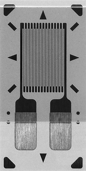
Figure 1: General-purpose etched metal-foil strain gauge.
An off-the-shelf discrete strain gauge is likely to comprise a metal foil, which is photo-etched to create a suitable directional strain-sensitive pattern and mounted on a polyimide or reinforced epoxy carrier, as shown in Figure 1. The type of metal alloy has a significant influence on the properties of the gauge. Constantan, sometimes called A-alloy, offers characteristics such as high strain sensitivity, as well as high resistivity allowing small sensor sizes. By also exhibiting relatively low temperature coefficient of resistance and stable mechanical performance over a wide range of strain levels and temperatures, constantan is usually the preferred alloy for use in general-purpose gauges. Another important advantage of constantan is that the alloy can be processed to achieve a specific value of self-temperature-compensation (S-T-C), to match the thermal expansion coefficient of a variety of test materials.
CEA series constantan general-purpose strain gauges by Micro-Measurements (a division of Vishay Precision Group) includes various models such as the CEA-06-125UN-350, which has an S-T-C number of 06 and nominal resistance of 350 Ω. The normal static operating temperature range for CEA series gauges is -75°C to 175°C, while for applications requiring a wider temperature range an LWK series nickel-chromium, or K-alloy, gauge such as the LWK-06-W250B-350 can operate from -195°C to 260°C.
The backing material and type of attachment are also important criteria for gauge selection. A polyimide or epoxy carrier is typically bonded to the test material using epoxy adhesive. In some applications, however, factors such as high operating temperatures or unfavorable environmental or test conditions that prevent curing of the adhesive or clamping of the gauge may drive engineers to use a weldable gauge. The Micro-Measurements LWK-06-W250B-350 is a weldable gauge, which is supplied pre-bonded to a thin metal carrier and with three lead wires already attached, allowing direct connection to the instrumentation cable. The gauge can be bonded to a cleaned metal test sample by spot welding.
Gauge size is a further important parameter to consider when selecting a strain gauge for a given application. Strain gauges naturally tend to integrate the force exerted over the entire length of the gauge. Since engineers often need to assess the peak stress experienced by a component part in a structure, applying an excessively long strain gauge in an area where the peak stress is concentrated in a small area can cause significant inaccuracy. On the other hand, very small sensors can be less stable and have lower maximum allowable elongation.
Positioning and connections
Strain gauges like the CEA-06-125UN-350 and LWK-06-W250B-350 are designed to be most sensitive to forces acting in line with the axis of the sensing grid. Hence, the orientation of the sensor, when attached to the test sample, is critical, and should be aligned with the direction of the force to be measured. If the direction is not known, a three-direction rosette-type gauge may be used.
Since the change in resistance under applied force is very small, a bridge-type measuring circuit is typically used with a precision voltmeter in order to ensure an accurate reading. The simple bridge circuit shown in Figure 2 is vulnerable to error caused by the resistances of the gauge lead wires. These can be compensated in a number of ways. The three-wire connection of the LWK series gauges can halve this error when the third wire is connected directly to the voltmeter, cancelling the effect of one of the two signal wires. An alternative approach is to connect strain gauges in both the upper and lower arms of the bridge, with opposing polarity so as to sense forces in opposite directions. In this arrangement both sets of lead resistance are cancelled, while the sensitivity of the system is doubled, thereby allowing even greater accuracy.

Figure 2: Basic bridge circuit for monitoring strain-gauge output.
Designing with load cells
Load cells used for force measurement are precisely engineered systems that contain multiple strain gauges configured as a bridge to ensure accurate and repeatable measurement. The strain gauges are bonded to a precision-engineered structural element, which may be made from a steel, aluminum or copper alloy. Precision design and machining ensures measurable and repeatable deflection, of magnitude proportional to the applied load, throughout the stated range. Load cells can be designed to measure bending, shear, compression or torsional force, and are available with a wide variety of operating ranges.
When selecting a load cell, engineers should pay attention to the specified safe load limit, as well as considering the operating load range. If an excessive overload is applied, the load cell can be permanently damaged and produce unreliable results in subsequent use. If an overload weight is anticipated, a load cell of higher capacity may be needed. Similarly, if appreciable shocks or dynamic loading are expected, derating of the load cell may be necessary.
Careful attention is also needed to design a suitable mounting system, bearing in mind that the load cell is a sensor and therefore should not be considered as a solid support. Care should be taken to avoid effects such as lateral forces, off-center loading or vibration. If more than one load cell is used in a system, special care may be needed to ensure that the load is evenly distributed to avoid unwanted disparities between the outputs from the individual load cells.
Measuring systems, from tons to pounds
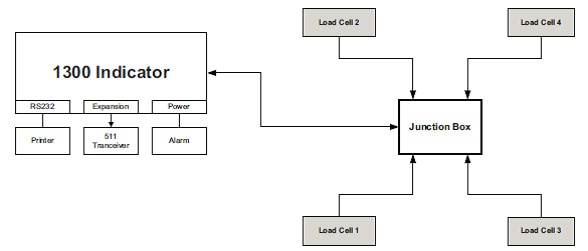
Load cells are available for a wide variety of applications. One example is in bulk weighing systems fitted to vehicles such as trucks. PM OnBoard, which, like Micro-Measurements, is also a division of Vishay Precision Group, produces a range of bulk weighing systems including safety-oriented systems and legal-for-trade systems that allow charging by weight for bulk materials at the point of loading or unloading. The BulkWeigh 1300 system for trucks weighing 17 to 44 tons has four or more load cells that are capable of monitoring individual axle weights, as shown in Figure 3, which can provide the driver with in-cab warning of an excessive or unbalanced load.

Figure 3: Use of load cells in an industrial-vehicle bulk weighing system.
At the other end of the extreme, miniature load cells such as the Measurement Specialties FC22 series are available with four standard measuring ranges from 0-10 to 0-100 lbf, and have two radial mounting holes spaced at 34 mm. These load cells are suitable for use in equipment such as robot end effectors to help control the force applied by the robot during various processes or to monitor the weight of any picked objects. Small load cells such as the FC22 can also be used in medical equipment such as controlling the linear force applied to a syringe infusion pump so as to control the dosing or transfer of fluids.
The FC22 series load cells are built using MEMS strain gauges, which sense strain via piezoelectric effects. Measurement Specialties has used its proprietary Microfused™ technology to bond the strain gauges to a stainless steel substrate by fusing with high-temperature glass. This eliminates organic epoxies, which can be age sensitive, and helps maximize stability and extends operating lifetime. This technology also helps ensure high sensitivity, even at low strains, as well as superior resolution and high over-range capability without requiring mechanical stops. The design of the FC22 eliminates fatigue mechanisms associated with other miniature force sensors, such as sensors that use pressure capsules. Thermal compensation is also built in, which eliminates temperature-related changes in zero and span.
Conclusion
Strain gauges and load cells each take advantage of changes in the electrical properties of a conductor or semiconductor when force is applied, to measure mechanical loading. All are precision instruments that must be designed-in carefully to ensure satisfactory performance. To achieve the desired accuracy, reliability and longevity are important not only to select the optimum component, but also to take care with positioning, orientation and fixing, as well as electrical connections. As always, greater understanding leads to better results.

免责声明:各个作者和/或论坛参与者在本网站发表的观点、看法和意见不代表 DigiKey 的观点、看法和意见,也不代表 DigiKey 官方政策。


