How to Use Energy Harvesting in the Industrial Internet of Things
投稿人:DigiKey 欧洲编辑
2016-05-17
Developing a system with an energy harvesting source can be a challenge, with low and irregular voltages giving designers a headache for supplying consistent power to a wireless sensor network used in the Industrial Internet of Things (IIoT).
Low cost and high reliability are more important in the Industrial IoT than data rates, and semiconductor vendors have put together their own evaluation systems to help designers work out the best way to use the energy around them to power their nodes from a variety of sources.
Using energy harvesting extends the use of rechargeable batteries from a year to ten, dramatically reducing the operating costs of an Industrial IoT network from having to replace the batteries in tens of thousands of sensors. This more than compensates for the additional complexity of the wireless node. In some cases, designers can even eliminate the battery entirely to save further costs and complexity in the network operation.
Some of the sources are more established than others. Photovoltaic solar cells are able to provide a regular supply of current at predictable voltages, even from the indoor fluorescent lighting that is found on the factory floor. This can be used with a power manager that is optimized for energy harvesting such as the ultra-low-power SPV1050 from STMicroelectronics that implements a maximum power point tracking algorithm (MPPT) with an input voltage range from 75 mA.
Alongside the MPPT function, the SPV1050 integrates the switching elements of a buck-boost converter, which allows it to charge off any battery, including the thin film batteries, by tightly monitoring the end-of-charge and the minimum battery voltage in order to avoid the overdischarge and to preserve the battery life.
The MPPT is programmable by a resistor input divider (see Figure 1) and allows maximizing the source power under any temperature and irradiance condition. An unregulated voltage output is available (e.g. to supply a microcontroller), while two fully independent low dropout regulators (LDOs) are embedded for powering sensors and RF transceivers to easily implement a node for the Industrial IoT. Both LDOs (1.8 V and 3.3 V) can be independently enabled through two dedicated pins to power those external devices.
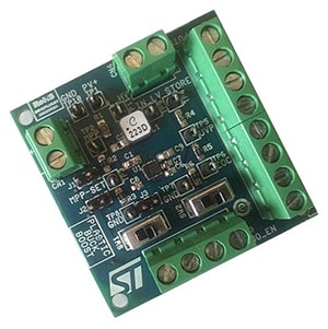
Figure 1: The SPV1050 from STMicroelectronics uses an MPPT controller for photovoltaic cells but can also be used with thermal energy generators.
However, the device is not just about PV cells, as the input voltage range from 75 mV up to 18 V and high efficiency in both buck-boost and boost configuration allows it to support thermal energy generation (TEG) sources. These generate current from a temperature difference, often using the Peltier Effect, and can have widely varying output voltages.
The SPV1050 also includes a trimming capability for the end-of-charge and undervoltage protection voltages to make sure that any source and battery are matched.
This is used on the STEVAL-ISV020V1 evaluation board (Figure2) that uses the SPV1050 to implement a buck-boost DC-DC converter with a particular set of jumpers and test points to help developers find the best system configuration.
The board is optimized for PV panels supplying between 2.6 V and 9 V, with an input current range of 10 mA to 20 mA. This is used to charge a battery with the 3.7 V undervoltage protection threshold (VUVP) and 4.2 V end of charge voltage threshold (VEOC).
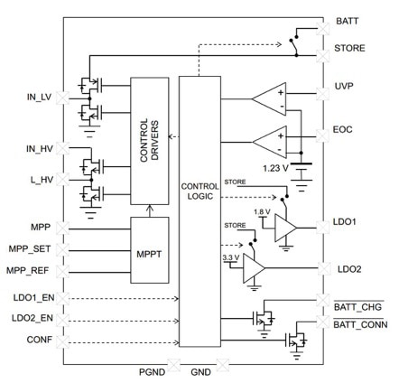
Figure 2: The STEVAL-ISV20V1 evaluation board allows different PV arrays and TEG sources to be used with the SPV1050 power manager.
By changing the input and output resistor partitioning, the CIN capacitor and the MPPT control VMPP_SET, different PV panels can be used. Changing the undervoltage and end of charge thresholds (VUVP down to 2.2 V and VEOC up to 5.3 V) can be easily done to support TEG sources and different battery loads.
Similarly, Analog Devices has used its energy harvesting evaluation board to help developers use its ADP5090 low voltage power manager for energy harvesting sources.
Analog Devices has developed a reference design for a multichannel data acquisition system using energy harvesting that is aimed at extremely compact form factors.
Powering such a system requires a wide range of other devices such as data converters and communications devices to be considered, which are configured and demonstrated on the evaluation board.
This includes the AD7091R-5 12-bit, ultra-low power, successive approximation analog-to-digital converter (ADC) that runs from a single 2.7 V to 5.25 V power supply, which needs to be matched to the power source and the battery.
The ADC also includes an on-chip conversion clock, an accurate reference, and an I2C interface that operates in both standard 100 kHz mode and fast 400 kHz mode to control the conversion process and data acquisition giving a maximum 22.22 kSPS throughput rate in fast mode.
The ADC has an autocycle mode that allows the user to configure the ADC for autonomous operation that is used for monitoring of events outside of a user-defined range. This is typically used to monitor a selection of channels with limit registers programmed to signal out of bounds conditions via the alert function.
To power this, the ADP5090 integrated boost regulator converts the power from PV cells or TEG sources with an input power range from 16 µW to 200 mW to charge a battery or supercapacitor, and the SYS voltage output of the ADP5090 supplies the entire circuit shown in Figure 3.
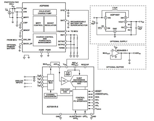
Figure 3: Combining the ADP5090 energy harvesting power manager with an ADC for a self-powered multichannel data acquisition module.
A key feature of the device to consider is the internal cold-start circuit, which allows it to start operating at an input voltage as low as 380 mV. The energy from a PV cell or TEG is introduced at ENERGY_IN, and when this exceeds 380 mV, the ADP5090 enters cold start-up. The device then exits cold-startup, and main boost is enabled when the SYS voltage exceeds VSYS_TH, which is typically 1.93 V. The logic high level (PGOOD) is equal to the SYS voltage, so when the battery terminal voltage is reached, the main boost charger is turned off. This then provides the flow of power through to the other devices on the board.
However there are optimizations to be made depending on the type of energy storage device used, and these are provided by the ratio of resistors on certain pins that are shown in Figure 4. These ratios need to be calculated for different supercapacitors and rechargeable batteries that support higher or lower energy requirements, but the reference circuit provides an excellent starting point for a battery-less sensor for the Industrial IoT.
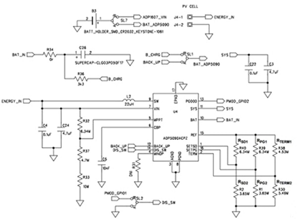
Figure 4: The energy harvesting circuit for the ADP5090 power manager.
The ADP5090 boost regulator operates in pulse frequency mode (PFM), transferring energy stored in the input capacitor to SYS and a 50 mF, 3.5 V supercapacitor. The PGOOD threshold is set by external connectors to indicate that the SYS voltage is at an acceptable voltage, given in Figure 5b where RPG1 and RPG2 are the values from Figure 4. VREF_ADP5090 is typically 1.21 V.

Figure 5a: Setting the PGOOD threshold for the AD5090
The ADP5090 is also equipped with battery overcharging and discharging protection thresholds, which are also set by external resistors. To prevent overcharging, the rising threshold for the battery terminal voltage is given in figure 5b where RTERM1 and RTERM2 are the values from Figure 4.

Figure 5b: Protecting a battery from overcharging and excessive discharge
To prevent deep discharge, the falling threshold for the battery discharge shutdown voltage is given in Figure 5c, where RSD1 and RSD2 are the values from Figure 4.

Figure 5c: The falling threshold for battery discharge shutdown to protect the rest of the circuit
This reference design eliminates the need for an external battery to power the circuit, and the CN-0372 board uses a super capacitor that supplies power for small electronic devices and battery-free systems that can sit anywhere in the Industrial IoT to collect data. Adding a rechargeable battery and varying the resistor ratios to protect it can provide higher peak current supply for adding other devices such as a wireless transceiver module.
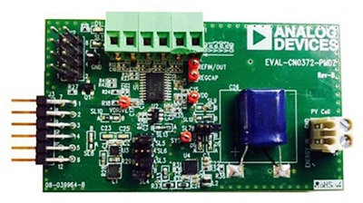
Figure 6: The EVAL-CN0372-PMDZ energy harvesting evaluation board from Analog Devices
Conclusion
Using evaluation boards to assess power management devices for energy harvesting are an essential tool, but there are still optimizations for the engineer to explore to get the most effective solution for their application. Modern power managers support photovoltaic cells or thermal generators to harvest energy from the environment and the evaluation boards demonstrate that it is possible to implement a battery-free sensor node with such devices, as well as systems with batteries to support higher peak current requirements. This gives Industrial IoT system designers significantly more flexibility in developing the nodes on the network without having to worry about the power supply.

免责声明:各个作者和/或论坛参与者在本网站发表的观点、看法和意见不代表 DigiKey 的观点、看法和意见,也不代表 DigiKey 官方政策。


