How the Simple DIN Rail Solves for Modularity, Flexibility, & Convenience in Industrial Systems
投稿人:DigiKey 北美编辑
2019-09-19
While engineers often use a standard 19 inch rack enclosure for their larger, multi-instrument test installations, this configuration is often not a good fit for industrial and laboratory situations. Instead, an arrangement is needed that can handle units of very different sizes, form factors, and interconnections; provide full and easy access from one side (the front); enable sufficient cooling and filtering for the often hot and dusty environment; support neat cable dressing with full labeling; and provide for physical protection and user safety where needed.
An alternative that meets these requirements and is better suited to the diverse needs of industrial installations is the DIN rail mounting system standard. This is a very widely used arrangement for mounting, accessing, and protecting the broad array, form factor, and size of electronic units needed by the application. It supports modules ranging from basic power supplies through advanced sensor interfaces to programmable logic controllers (PLCs), with thousands of DIN-compatible products available from hundreds of vendors. It is designed for flexibility and ease of installation, connection, and access in industrial and other installations.
This article looks at this worldwide metric-based mounting system, and using sample solutions, shows how designers can take advantage of its attributes and versatility.
Basics of the DIN rail
Exactly what is the “DIN rail”? It’s a mounting rail for electronic modules that can be used for power supplies as well as many other functions—such as circuit breakers, programmable logic controllers, proportional-integral-derivative (PID) controllers, loop transmitters and receivers, motor drives, relays, and metering units, to cite a few—all of which are available with DIN rail mounting capability (Figure 1).
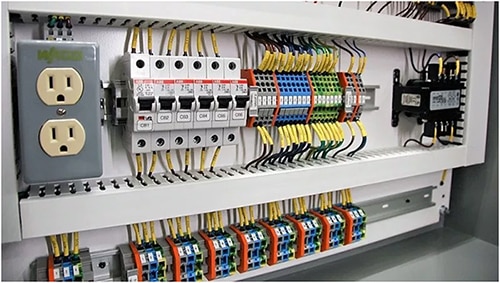 Figure 1: The DIN rail handles a diverse array of module sizes and functions, including power supplies, transducer I/O, and communications interfaces at low to high point counts; it is well suited to a neat, organized, and labeled cable arrangement and dressing. (Image source: VPEL)
The acronym "DIN" derives from the specifications published by Germany's DIN—Deutsches Institut für Normung, or German Institute of Standards—which have since been adopted as European (EN) and international (IEC) standards. The DIN rail standard was initiated in the late 1950s and the same standard has also been adopted by the North American Electrical Manufacturers Association (NEMA).
DIN rails are made from cold rolled carbon steel sheet, aluminum, or polycarbonate, with various plating and finishes for corrosion resistance where needed. Different materials also have different short-circuit and fault current ratings, a consideration in some settings.
The DIN rail is widely used as an open standard mounting arrangement. Users of this rail are not committed or tied to any single vendor or group, as hundreds of vendors offer thousands of DIN rail products.
There are three standard DIN rail configurations, with the most widely used by far being the 35 millimeter (mm) wide IEC/EN 60715 version, commonly called the “top hat” rail profile (Figure 2). It is also called the TS35 rail in the United States, although the DIN name is used more often. The predecessor of the “top hat” version is the asymmetric G profile, generally used to hold heavier, higher power components; there is also a C profile.
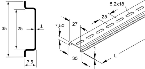 Figure 2: The basic profile of the EN 60715 7.5 mm DIN rail is shown on the left. More detailed dimensions of the “top hat” rail as well as standard panel attachment perforations are shown on the right. (Image sources: Wikipedia (left), elektrotools.de (right))
Originally designated as DIN EN 50022, and subsequently standardized as IEC IEC/EN 60715, the standard calls out both 7.5 mm and 15 mm deep versions. The modules that the rail supports are mounted side by side in any arrangement or configuration that the user prefers for the application; users are unrestricted and can put the power supply at the left, right, or center to supply the loads, doing whatever works best in the situation.
DIN rails are available in standard lengths such as one and two meters or can be custom cut to any desired length which is useful for unique projects. The standard also defines for, but does not mandate, standard cutout slots (called perforations) for ease of attachment to a panel. For example, Altech Corporation offers its CA601/S “top hat” rail measuring 15 mm deep (Figure 3). The rail is available in zinc plated steel, stainless steel, and aluminum in lengths of one and two meters, as well as custom lengths.
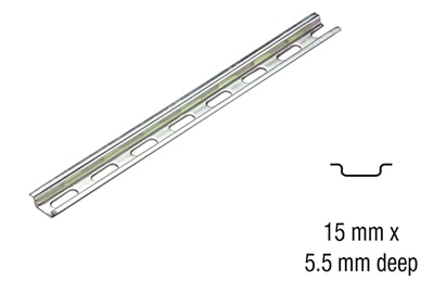 Figure 3: The CA601/S DIN rail from Altech Corporation is available in a wide range of lengths and material options. (Image source: Altech Corporation)
The rail plus its modules are usually mounted in a rack or equipment cabinet for physical integrity and safety. However, it can also be mounted to a wall or other horizontal surface if it makes more sense in a specific application for visibility and physical access. Vendors also offer a wide array of interconnection terminal blocks, brackets, clips, and other items that facilitate DIN rail use. Also, if perforations are not required, there are options available without them.
Note that the DIN rail is just that: a mounting rail and not an interconnection bus, although the rail may provide a chassis grounding connection. The various units mounted via the rail are then interconnected with discrete cables. While this may seem to be less convenient and more work than a standard “plug in the cards” backplane bus, it is actually a benefit in many industrial applications.
This is because there is no bus to limit or define the voltage, current, type (AC or DC), or total amount of power that can be supplied to the various modules. Further, a defined bus—which has its well-known benefits in embedded systems—would constrain the type and number of highly diverse data channels needed, such as having dozens of analog 4-20 milliamp (mA) loops together with Ethernet data paths, to cite two “extremes” of signal speed and type.
The DIN rail has been especially beneficial for power supplies with their wide array of voltage/current ratings and corresponding size and power ratings differences. It offers flexibility and possibilities for all parties: supply vendors, specifiers, and users. Some power supplies and other modules (such as PLCs) are designed specifically for DIN rail, but many can serve both rail and non-rail applications with the addition of a simple, low-cost mounting kit.
This is an advantage for supply and module vendors, as it allows offering the same unit in multiple end product form factors; doing so reduces the number of distinct units that need to be built and stocked, thus simplifying the repair and replacement supply chain and shortening repair and upgrade time.
The DIN rail does not define the I/O cable routing for the modules which it holds. However, DIN rail devices such as PLCs, sensor/actuator interfaces and loops, and other interconnection modules generally have inputs located on the top and outputs on the bottom. Again, since the DIN rail is only a mounting rail, it can accommodate specialized situations where the common arrangement is impractical or undesired.
Available modules: a wide assortment
Every project has a power supply, and DIN rail supplies are available covering AC and DC inputs with outputs that span low, moderate, and high AC and DC voltages at various power levels. For example, the DRC-5V10W1AZ from Delta Electronics is a basic, single output, fully enclosed AC/DC converter delivering 5 volts at up to 1.5 amperes (A) for a total of 7.5 watts from a package measuring 91 x 56 x 18 mm (Figure 4).
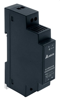 Figure 4: The DRC-5V10W1AZ from Delta Electronics is a double isolated, low-power AC/DC DIN rail power converter, delivering 7.5 watts from a package measuring 91 x 56 x 18 mm. (Image source: Delta Electronics)
This universal input supply operates on voltages ranging from 90 to 264 volts AC, and features Class II, double isolation, so no earth connection is required. The unit delivers full power up to 55°C without derating over the entire input voltage span. Efficiency is better than 78% with a 115 volt AC input and it includes the full list of protection features including overvoltage, overcurrent, and over-temperature protection.
PLCs are widely used in industrial and process control, so there’s a wide selection of DIN mountable units on the market. One interesting approach is provided by the ZEN-10C1DR-D-V2 series from OMRON Automation and Safety. This is a basic, low count PLC with modular add-ons to increase the channel count while retaining the core processor and user interface (Figure 5).
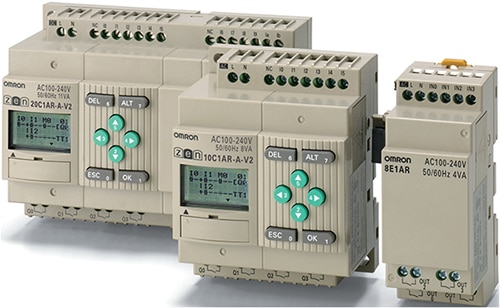 Figure 5: The PLC is a common module in DIN rail systems. The Omron ZEN-10C1DR-D-V2 series unit begins as a base unit with a processor, transducer I/O, and LCD user interface. It can be expanded in steps of 10 I/O points via modules that attach alongside and extend the core unit. (Image source: OMRON Automation and Safety)
The basic unit is housed in a compact body measuring 70 x 90 mm and Omron has made it easier to program by incorporating a graphical LCD screen and eight operation buttons. This 24 volt unit provides relay, timer, counter, and time switch functions in addition to its six inputs and six outputs. Expansion modules measuring 35 mm wide are available that attach to the basic unit and increase the I/O count to 44 points in steps of ten. Other expansion modules support additional communications interfaces such as RS-485.
Power and dissipation issues
Thermal issues must be assessed when using the DIN rail, especially when using it in cabinets or other enclosures. Since the DIN rail standard does not define a maximum power level or the physical arrangement of multiple power supplies (if any), it’s important to look at both the total heat load and the distribution of the heat sources.
The former can be checked fairly simply by looking at the supply’s rating, as the maximum heat generated (watts) cannot exceed that value. Next, the ambient temperature is factored into the analysis. However, the unconstrained arrangement of the various modules on the DIN rail means that a higher dissipation module (typically a power supply, but not necessarily) might be situated adjacent to a heat-sensitive module, so the thermal floor plan must be checked as well.
Engineering is largely about trade-offs and standards, and no solution or format is “perfect” for every application. Despite its flexibility, the DIN rail approach is not the “universal” answer to using larger, heavier units such as power supplies. In practice, the DIN rail is suitable for dissipation up to about 1000 W in a closed, rack width enclosure, unless substantial forced air or active cooling is available. If larger supplies are used, they are sometimes mounted “off rail” due to their weight and size, but there also are many rail-compatible ones for relatively higher power ratings.
Also, the DIN rail and its supplies may not be a good choice when the power supply or other modules need to have multiple user readouts for parameters such as voltage and current, indicators for various status and fault conditions such as power good or overload, or I/O status and alarms. This is because DIN modules tend to be narrow with more use of depth than width, thus limiting the availability of front panel space for user readouts.
Modules with more indicators and readouts are available, but they are generally wider and take up more of the rail real estate. Fortunately, the flexibility and non-bus nature of the DIN rail allows for an easy solution to this problem by simply using two (or more) rails, with one mounted below the other and linked by cabling as needed.
Conclusion
The DIN rail mounting system standard offers flexibility and ease of use for designers, vendors, and buyers of industrial systems and industrial system modules. It supports modules ranging from basic power supplies through advanced sensor interfaces to PLCs, with thousands of DIN-compatible products available from hundreds of vendors.
References
- Hackaday, “The DIN Rail and How it Got That Way”
- International Electrotechnical Commission, “IEC 60715:2017: Dimensions of low-voltage switchgear and controlgear - Standardized mounting on rails for mechanical support of switchgear, controlgear and accessories”
- ATMCO LLC, Model LB-100 DIN Rail Cutter

免责声明:各个作者和/或论坛参与者在本网站发表的观点、看法和意见不代表 DigiKey 的观点、看法和意见,也不代表 DigiKey 官方政策。


