Design Trade-offs when Selecting a High-Frequency Switching Regulator
投稿人:电子产品
2015-02-24
Since the 1980s, DC-to-DC switching voltage converters (“switching regulators”) have become popular for battery-powered applications because of their inherent higher efficiency compared to linear regulators. This attribute allows batteries to last longer and circuits to stay cooler.
Over time, manufacturers have increased the frequency at which the regulator switches from a few hundred kilohertz to three or four megahertz. The key benefit of operating at higher frequency is that it allows the use of smaller external components, such as inductors and capacitors, saving board space and component costs.
Unfortunately, higher-frequency devices are less efficient than their slower-switching counterparts, forcing engineers to trade-off size and cost advantages against shorter battery life. However, a new generation of high-frequency voltage regulators takes advantage of modern process technology to improve performances.
This article takes a closer look at the trade-offs when designing a power supply based on a high-frequency regulator and describes some examples of new highly-efficient chips from the major silicon vendors.
Switch for efficiency
Linear regulators are simple and effective devices for regulating a battery voltage to that demanded by sensitive silicon. However, they suffer from two key drawbacks. First, efficiency declines as the difference between input and output voltage increases. Second, linear regulators can only step-down (“buck”) rather than step-up (“boost”) or invert a voltage. This failure to boost voltages can leave untapped potential in the batteries when the device can no longer be powered (see the TechZone article “Understanding the Advantages and Disadvantages of Linear Regulators”).
These weaknesses have seen the rise in popularity of switching regulators. Entering the mainstream in the 1980s, switching regulators employ a pulse-width-modulated (PWM) switching element comprising one or two metal-oxide semiconductor field-effect transistors (MOSFETs) paired with one or two inductors and capacitors for energy storage and filtering.
When the transistor is on and conducting current, the voltage drop across its power path is minimal. When the transistor is off and blocking high voltage, there is almost no current through its power path. Consequently, the transistor is close to an ideal switch and power dissipation is minimized.
High efficiency, low-power dissipation, and high-power density (because of their small size) are the main reasons for designers to use switching regulators instead of linear regulators, especially in high-current applications. Moreover, switching regulators are able to boost, buck, and invert voltages. Many manufacturers offer wide ranges of modular chips that integrate the primary elements of a switching regulator into a single device that is compact, reliable, and easy to design in.
The efficiency of such a device (output power/input power x 100) is typically above 80 percent and can be as high as 95 percent. Wasted power is typically dissipated as heat.
While the operating frequency determines the number of switching cycles per unit time, it is the duty cycle (D) of the PWM signal that determines the percentage of the time that the switching element conducts and therefore, in turn, the output voltage (VOUT) from the formula VOUT = D x VIN. The operating frequency does, however, significantly influence the design and performance of the regulator.¹
To suit various applications, manufacturers supply switching regulators operating across a range of frequencies from 100 kHz to 4 MHz. At the low-frequency end, for example, Linear Technology supplies the LT1574. This is a 200 kHz current-mode switching regulator suited for 9 to 5 V, 5 to 3.3 V and inverting operation that the company says is useful for noise-sensitive products.
Positioned at the top end of the company’s range is the LTC3601. The chip is a current-mode switching regulator capable of supplying up to 1.5 A of output current. The operating supply voltage range is from 4 to 15 V and the operating frequency is programmable up to 4 MHz, which the company says enables the use of small surface-mount inductors.
The trade-offs of high-switching frequencies
Figure 1 shows a typical switching regulator in a buck configuration. In this circuit, the inductor acts as an energy-storage device. When the transistor is powered, current flows from the input source, through the transistor and inductor, to the output. The magnetic field in the inductor builds up, storing energy. The voltage drop across the inductor (which is proportional to the duty cycle of the transistor) opposes (or “bucks”) part of the input voltage. When the transistor switches off, the inductor opposes the change by flipping its electromotive force (EMF) and supplies current to the load itself via the diode.

Figure 1: Typical switching regulator in a buck configuration. (Courtesy of Linear Technology)
Similar things happen in a boost converter. Specifically, current flows from the input when the transistor is switched on. This passes through the inductor and transistor, with energy being stored in the inductor’s magnetic field. There is no current through the diode, and the load current is supplied by the charge in the capacitor. Then, when the transistor is turned off, the inductor opposes any drop in current by reversing its EMF, boosting the source voltage and current. Current flows from the source through the inductor and diode to the load, as well as recharges the capacitor (see the TechZone article “The Inductor's Role in Completing a Power Module-Based Solution”).
Although the output voltage is not influenced directly by the switching frequency, the rate of switching does have a significant effect on the power supply design. In general, higher switching frequency allows the use of a smaller-inductor (and input- and output-filter capacitors). This is because the inductor size is primarily determined by the amount of ripple current allowed in a given switching regulator’s specification. For a given inductance, the ripple current decreases as the switching frequency increases. Consequently, a progressively smaller inductor can be used to maintain the same amount of ripple current as a switching regulator’s frequency increases – reducing the size and cost of the power supply.
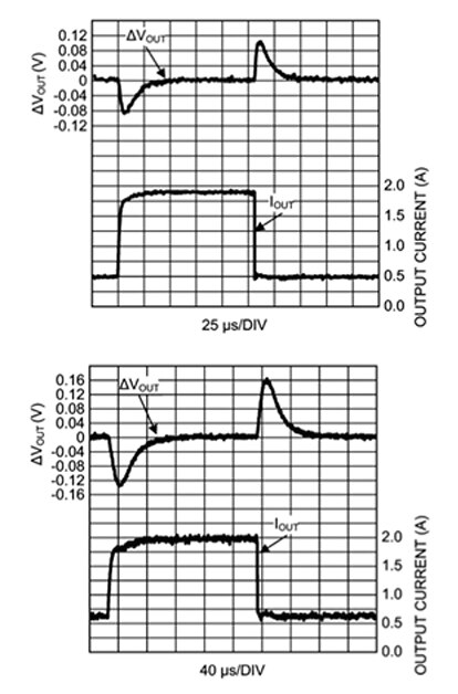
Higher-frequency operation also endows the switching regulator with greater bandwidth, boosting the device’s transient response (Figure 2).

Figure 2: Higher-frequency operation improves transient response (2.2 MHz device at top, 550 kHz device at bottom). [Courtesy of Texas Instruments]²
Another benefit of switching at a frequency as high as 4 MHz is that it enables designers to avoid critical noise-sensitive frequency bands, such as AM radio. However, there is a trade-off. For example, electromagnetic interference (EMI) can be problematic when operating at high-switching frequencies. EMI from a switching regulator is proportional to the square of the switching frequency – in other words, if the switching frequency doubles, the EMI can increase fourfold. Paying close attention to the printed-circuit-board (PCB) layout and component selection can mitigate EMI problems² (See the TechZone article “Capacitor Selection is Key to Good Voltage Regulator Design”).
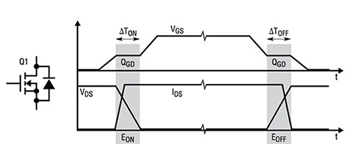
Higher-switching frequency also means greater power loss, demanding more board space or a heatsink to dissipate the heat. Switching loss increases with greater frequency due to the larger number of constant-energy-switching events per time.³ Some of these losses are due to the switching regulator’s MOSFET which takes a finite time to be turned “on” or “off.” This generates voltage and current overlaps during the switching transients. Figure 3 shows the typical switching waveforms of a switching-regulator MOSFET. The main switching losses are due to the charging and discharging of the MOSFET’s parasitic capacitance with charge (QGD). The MOSFET’s switching loss (PSW) is proportional to the converter switching frequency (fS) from the formula:
![]()

Figure 3: Typical switching waveform and losses in the MOSFET of a buck regulator. (Courtesy of Linear Technology)
Although higher-switching frequency allows the use of a smaller inductor it also increases the loss directly in that component. Inductor AC loss is primarily generated by the magnetic core. In a high-frequency switching regulator the core material is typically powdered iron or ferrite. Powdered iron suffers from greater losses than ferrite but in either case the losses are mainly due to magnetic hysteresis.
Other AC-related losses include the gate driver loss and the dead-time body-diode conduction loss. The calculation of switching losses is usually not simple but it is easier to see that they are proportional to switching frequency.
For applications greater than 10 A load current, most buck-switching regulators operate in the 100 kHz to 2 MHz range. For example, Texas Instruments’ (TI) TPS53353, a synchronous-buck-switching regulator, delivers up to 20 A at 1.5 to 15 V from a 4.5 to 25 V input and features an adjustable 250 kHz to 1 MHz switching frequency.
For lower than 10 A load current, when there is less power to dissipate, the switching frequency can increase to 3 or 4 MHz. Maxim, for example, offers the MAX8560, a synchronous-buck-switching regulator that features a switching frequency of 4 MHz. The device can operate from a 2.7 to 5.5 V input and provides a 0.6 to 2.5 V output at up to 500 mA.
The optimum frequency for each design is a result of careful trade-offs in size, cost, efficiency, and other performance parameters.
Narrowing the gap
The actual switching losses in a regulator depend on the topology, components, and the application. Not so long ago a synchronous buck converter running from a 12 V input and producing a 3.3 V/10 A output might suffer a one percent loss in efficiency for each 100 kHz increase in frequency. Therefore, for otherwise similar devices, if a 200 kHz switching regulator had an efficiency of 93 percent, a 500 KHz product would exhibit an efficiency of 90 percent while a 2 MHz switching regulator would struggle to hit 75 percent.
The good news is that power-module manufacturers have recently focused their efforts on improving the efficiency of high-frequency switching regulators – with some spectacular results.
The improvement is primarily due to lower conduction and switching losses in the MOSFETs. These losses have been reduced by improving the figure of merit (FOM) of the power transistor, which translates to lower channel resistance and less gate-drive charge. New design methodologies have produced regulator designs with faster switching edges, further lowering the losses during MOSFET transitions.
These changes have narrowed the gap between high-frequency switching regulators and low- to mid-frequency devices. TI, for example, offers two version of its LM26420. The module is a dual 2 A, high-frequency synchronous buck regulator operating from an input range of 3 to 5.5 V. The output ranges from 0.8 to 4.5 V with 2 A output current per regulator. The device is available in 550 kHz and 2.2 MHz versions.
Figure 4 shows that when converting from an input voltage of 5 V to an output voltage of 1.2 V at 2 A, the peak efficiency is only three percent less for the 2.2 MHz frequency option (at 87 percent) compared to the 550 kHz device.

Figure 4: Efficiency of TI LM26420 at different switching frequencies (2.2 MHz device at top, 550 kHz device at bottom). [Courtesy of Texas Instruments]
Similarly, Intersil offers its ISL8002 in 1 or 2 MHz versions. The ISL8002 is a synchronous-buck switching regulator that can deliver up to 2 A of continuous output current from a 2.7 to 5.5 V input supply. At a switching frequency of 1 MHz, with VIN = 3.3 V, VOUT = 1.5 V, and an output load of 200 mA, the efficiency is 94 percent. Under the same operating conditions, the 2 MHz version exhibits an efficiency of 92 percent.
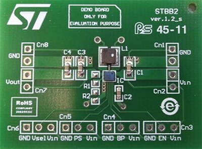
For its part, STMicroelectronics offers a 2.5 MHz dual-mode buck-boost switching regulator with equally impressive efficiency. The STBB2 provides output voltages from 1.2 to 4.5 V with input voltages from 2.4 to 5.5 V. With VIN = 4.5 V, VOUT = 2.9 V, and an output load of 200 mA, the efficiency is 91 percent. To help designers the company also offers its STEVAL-ISA109V2, designed to aid in the evaluation of the STBB2 (Figure 5).

Figure 5: STMicroelectronics STBB2 switching-regulator evaluation board.
Less of a compromise
High-frequency switching regulators appeal to design engineers because they enable more compact designs and better transient response. However, in return for these benefits the designer was previously faced with a tougher EMI challenge and a reduction in efficiency, shortening battery life and increasing operating temperatures.
However, due to improved design and better process technologies, contemporary power modules have addressed at least one of those drawbacks. By careful selection, the engineer can now enjoy the benefits of more compact design without having to suffer a 10 to 15 percent efficiency deficit. Modern high-frequency components are now just a few percent less efficient than switching regulators running at a quarter of the frequency.
For more information on the parts discussed in this article, use the links provided to access product pages on the DigiKey website.
References:
- “Basic Concepts of Linear Regulator and Switching Mode Power Supplies,” Henry J. Zhang, Linear Technology, Application Note 140, Oct 2013.
- “Benefits and Challenges of High-Frequency Regulators,” Texas Instruments, Application Report AN-1973, April 2013.
- “Effects of High Switching Frequency on Buck Regulators,” ON Semiconductor.
免责声明:各个作者和/或论坛参与者在本网站发表的观点、看法和意见不代表 DigiKey 的观点、看法和意见,也不代表 DigiKey 官方政策。


 中国
中国