Active Versus Passive Temperature Sensors: Designers Need to Choose Carefully
投稿人:DigiKey 北美编辑
2016-07-27
Knowing the ambient or remote temperature of a critical component is a vital part of many systems and there are a wide variety of devices available for the designer to use. However, not all temperature sensing devices are right for any given task, and choosing the wrong one can be costly in terms of accuracy, project schedule and product cost.
In this article we will describe the characteristics of often-used passive and active temperature sensors, including their advantages and limitations, to help you narrow the selection of components to consider for the design problem at hand. A deeper dive into some recent integrated temperature sensor ICs will show how these advanced sensors can help solve multiple design problems for many applications such as embedded computing, appliances, IoT and wearables.
Sensor types
The thermistor (from: therm-ally sensitive res-istor) is a resistor with properties that enhance its change of resistance with temperature. Negative temperature coefficient (NTC) versions, which have lower resistance at higher temperatures, are the most common but they also come in positive temperature coefficient (PTC) flavors. They are made from a ceramic semiconductor material and are designed to have fast response times, high accuracy and good repeatability.
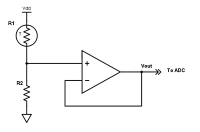
However, they are non-linear devices with an exponential change with temperature and there is a tradeoff between linear range and accuracy. When an NTC thermistor is connected in a resistor divider arrangement, as shown in Figure 1, the resulting current is linearized and Vout varies linearly with temperature over a limited range (typically about 60°C). If R2 is chosen to be equal to the thermistor resistance at +25°, then the output will be symmetrical around the +25°C point.

Figure 1: A voltage-mode bias circuit to linearize a thermistor output. If R2 is chosen to be equal to the thermistor resistance at +25°C, then the output will be symmetrical around the +25°C point. (Image generated using DigiKey’s Scheme-it block diagramming and schematic tool)
Thermistors can be chosen for larger linearity ranges at the expense of sensitivity. They are passive devices that require a current passing through them to produce a measurable output. Self-heating from the current flow can add an offset to the measurement which must be accounted for in some applications. Higher precision generally comes at a cost, including increased circuitry, careful analog design, and calibration.
The resistance temperature detector (RTD) is another type of sensor using change of resistance to detect temperature. RTDs are made from high-purity metals wound into a coil, or deposited as thin-films on a ceramic substrate. They are PTC devices and a constant current passing through the device will generate a temperature-varying output that is extremely linear and very accurate.
Self-heating will again have to be factored out. RTDs have poor thermal sensitivity so a change in temperature produces a very small output change. This makes them useful when sensing a wide temperature range (-200°C to +750°C for example), although the linearity deviates at the extreme ends and can be accounted for by look-up tables if needed.
The thermocouple consists of two junctions of dissimilar metals welded or crimped together. One of these junctions is connected to a reference temperature (cold) and the other to the measuring point (hot). The different properties of the two metals produces a “thermo-electric” effect where the voltage across the junction varies with temperature. Extreme temperatures can be measured this way (from as low as -200°C to over +2000°C). With such a wide range, the output voltage change with temperature is only a few millivolts/10°C, so output amplification is required. The amplifier needs to have good drift stability to prevent recalibration to maintain precise measurements.
All these passive sensor types require additional signal conditioning to interface them to the control electronics. Since their outputs are relatively low-level analog signals, care must be taken to avoid noise pickup from other circuits or the environment. If high accuracy and noise tolerance are required, the external sensor circuit complexity can grow quickly.
IC sensors are active semiconductor devices whose output is a voltage or current proportional to a temperature and can provide analog or digital outputs. Since they are integrated circuits, a myriad of features can be built-in to provide a stable, consistent linear output across a temperature range that is suitable for many applications (-55°C to +200°C). They also have power advantages – a simple IC sensor needs only a few µA of power, where a thermistor bias circuit can require several hundred µA. They vary in complexity and cost and are suitable for a wide range of applications including computing systems, wearables, data loggers and automotive.
A summary of the different sensor types is shown in Table 1.
| Characteristic | Thermistor | RTD | Thermocouple | IC sensor |
| Temperature Range | -100 to +500°C | -250 to +750°C | -200 to >+2000°C | -55 to +200°C |
| Linearity | Worst | Good | Poor | Best |
| Accuracy | Calibration Dependent | Best | Good | Good |
| Sensitivity | Best | Less | Worst | Good |
| Power Consumption | High | High | Low to High | Lowest |
| External Circuitry | Simple unless high accuracy/low power needed | Complex | Complex | Simplest |
| Typical Applications | Low precision, moderate temp range – toasters, hair dryers, protection circuits | High precision, extended temperature – gas and fluid flow | Extreme temperature sensing –ovens, kilns, test equipment | Computers, wearables, data logging, automotive |
Table 1: A comparison of sensor types. Passive sensor elements can operate over large temperature ranges. IC sensors offer good performance and value over a more limited range.
Precision sensing, small package
IC sensors can rival passive sensors in accuracy, linearity, design complexity, and cost when the range of temperature sensing is not extreme. An example of this is the LMT70 precision analog temperature sensor from Texas Instruments (Figure 2).

Figure 2: The LMT70 four-pin temperature sensor with analog output. Its high precision makes it an excellent replacement for RTD and precision NTC thermistors in many applications. (Image courtesy of Texas Instruments)
The LMT70 is a four-pin device that converts temperature to voltage using on-board stacked bipolar junction transistor (BJT) base-emitter junctions, biased by a current source. The temperature analog output, TAO, is switched by T_ON, allowing multiple LMT70s to share the same analog-to-digital (A/D) converter input. TAO is a low-impedance push-pull output that is ideal for driving the input capacitance of switched ADC loads.
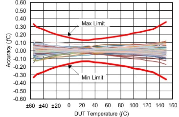
The LMT70 is an excellent replacement for RTD and precision NTC thermistors in applications that do not require extreme temperature measurement. It can provide an impressive +0.13°C accuracy from 20°C to 42°C in a 4-pin package measuring 0.88 x 0.88 mm, making it ideal for sensing body temperature in medical, fitness and wearable applications.
Across its full temperature range of -55°C to 150°C, the accuracy is +0.36°C and its wide input supply range of 2.0 V to 5.5 V make it suitable for Internet of Things (IoT) sensor, precision instrumentation and automotive applications. The small package size makes it possible to embed the sensor in a probe tip for remote sensing applications.
The stacked BJT sensor has good linearity across a 10°C range, but to get the accuracy noted above, some computational help is needed. TI makes this simple by providing a look-up table (LUT) of min/max and average TAO readings in mV for every 10°C temperature point. Between these values, a simple linear interpolation will yield the accuracy results shown in Figure 3.

Figure 3: The LMT70 temperature accuracy graph: the red lines show the min and max limits using a look-up table and linear interpolation for conversion of voltage to temperature. The other lines show individual device performance. (Image courtesy of Texas Instruments)
If you have more compute power available, the accuracy can be improved at the low and high ends of the range by using 2nd- and 3rd-order equations provided by TI in the data sheet. Example software routines for linear interpolation and the 2nd-order equation are included in Appendix A of this article.
One thing to keep in mind is that the actual temperature being measured is the junction temperature of the die, which means it is offset by the thermal resistance junction-to-ambient (RΘJA) which is 187°C/W for the LMT70. Equation 1 is the local temperature rise of the device as given in the data sheet:
![]()
Where:
TA is the ambient temperature
IO is the quiescent current
VTAO is the voltage on TAO
IL is the load current on TAO
With no load on TAO, the input device self-heating is minimal (at 3 V VDD and max quiescent current, the temperature rise is only 187°C/W x 3 V x 12 µA = 0.007°C). If the output is enabled for a significant fraction of the time the load dependent self-heating will need to be included in the offset calculation. For wearable and medical applications, the thermal conductivity of the board material and product package also need to be considered.
Going all digital
While analog-output IC sensors go a long way toward minimizing external circuit complexity, the output still needs to be digitized with an external A/D converter. The output is also subject to noise that can impact the accuracy of the measurement, especially in remote sensing applications. Switch-mode power supplies and backlight inverters can generate high switch-related interference that can be difficult to filter out. For those cases, a digital output sensor can be the right solution.
The MCP9902 from Microchip Technology is a new multi-channel remote temperature sensor with built-in internal temperature monitoring. It uses the industry-standard System Management Bus (SMBus) to report temperature measurements to the system controller. The sensor supports one internal and one external measurement using diode junctions for sense elements. There are two sister devices: the MCP9903, which adds an additional external sensor input, and the MCP9904, which supports a total of three external sensors.
Although not as small as the LMT70, the MCP9902 packs a lot of functionality into a 2 x 2 mm ultra-thin package. Temperature accuracy is +1°C from -40°C to +65°C and +2°C from +65°C to +125°C, which makes it particularly applicable to lower temperature-sensing requirements such as refrigeration and outdoor equipment monitoring.
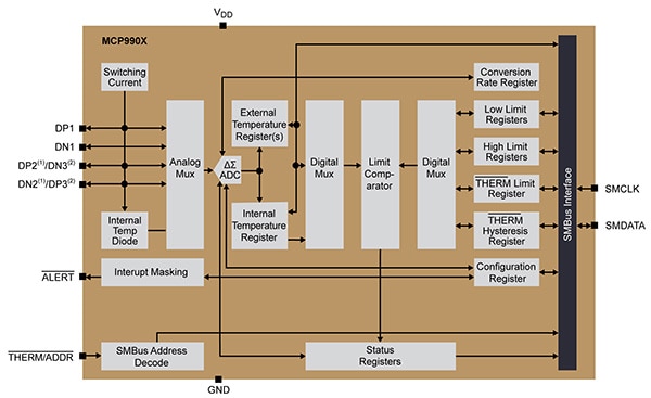
A quick look at the MCP9902 block diagram in Figure 4 emphasizes the level of digital features of the device. It is highly configurable via the SMBus pins – SMCLK and SMDATA – which are used to set limit points, offset and compensation parameters, and select conversion rates and options for lower power or improved noise rejection. The SMBus also reports temperature measurement data and faults.

Figure 4: Block diagram of Microchip’s MCP990x family of digital-output temperature sensors. The MCP9902 is a two-channel device, the MCP9903 has 3 channels, and the MCP9904 is a 4-channel part. (Image courtesy of Microchip Technology)
The sensor portion of the die operates on the fundamental principle of the change of diode forward bias voltage (ΔVBE) when it is operated at two different currents. This is described by Equation 2:
![]()
Where:
k = Boltzmann’s constant
T = Absolute temperature in degrees Kelvin
q = Electron charge
ƞ = Diode ideality factor
Discrete diodes are not used for the measurements. Instead small-signal transistors, such as the 2N3904 or 2N3906, with the collector-base junctions tied together or substrate diodes embedded in processors or FPGAs, have better characteristics. Figure 5 shows typical connection configurations.

Figure 5: Application diagram for the Microchip MCP990x family of remote temperature sensors. Small-signal BJT devices with the collector-base junctions tied together are used for the external sense elements. (Image courtesy of Microchip Technology)
During a measurement, the IHIGH and ILOW bias currents are automatically switched to a sensor input via the switching-current block, and the resulting voltage differential is fed to the high-speed ΔΣ A/D converter. On-board hardware uses the result to solve Equation 2 for T. The default diode ideality factor used is 1.008, but a range of other values is selectable via a register to minimize ideality factor temperature mismatch.
The measurement result is deposited in the temperature registers, which can be read by the SMBus. High and low limit registers are also available that can be used to set maskable alert points for thermal warnings or a non-maskable thermal limit output which can be used for thermal shutdown purposes.
External diode pin faults are detected by the device and can be reported via the Alert/THERM2 pin and the Fault bit in the Status register. The external channel numbers experiencing faults are shown in the External Diode Fault Register. The Status register also reports when internal and external measurements exceed the programmable limits.
Other programmable features, which reduce external circuitry, are digital filtering and dynamic averaging for noise reduction and parasitic resistance error correction to improve accuracy. Parasitic resistance can come from long remote sensor wires, PCB trace resistance, or the parasitic components of on die sensors. Up to 100 Ω of series resistance can automatically be corrected by the device.
Conclusion
For extreme temperature sensing or simple low precision thermostat applications, thermistors, RTDs and thermocouples still have their place in the designer’s toolbox. Today’s IC sensors offer small form factor low external circuit solutions with high precision that can simplify designs for temperature ranges found in many applications.
Appendix A
Courtesy Texas Instruments
/* --COPYRIGHT--,BSD
* Copyright (c) 2015, Texas Instruments Incorporated
* All rights reserved.
*
* Redistribution and use in source and binary forms, with or without
* modification, are permitted provided that the following conditions
* are met:
*
* * Redistributions of source code must retain the above copyright
* notice, this list of conditions and the following disclaimer.
*
* * Redistributions in binary form must reproduce the above copyright
* notice, this list of conditions and the following disclaimer in the
* documentation and/or other materials provided with the distribution.
*
* * Neither the name of Texas Instruments Incorporated nor the names of
* its contributors may be used to endorse or promote products derived
* from this software without specific prior written permission.
*
* THIS SOFTWARE IS PROVIDED BY THE COPYRIGHT HOLDERS AND CONTRIBUTORS "AS IS"
* AND ANY EXPRESS OR IMPLIED WARRANTIES, INCLUDING, BUT NOT LIMITED TO,
* THE IMPLIED WARRANTIES OF MERCHANTABILITY AND FITNESS FOR A PARTICULAR
* PURPOSE ARE DISCLAIMED. IN NO EVENT SHALL THE COPYRIGHT OWNER OR
* CONTRIBUTORS BE LIABLE FOR ANY DIRECT, INDIRECT, INCIDENTAL, SPECIAL,
* EXEMPLARY, OR CONSEQUENTIAL DAMAGES (INCLUDING, BUT NOT LIMITED TO,
* PROCUREMENT OF SUBSTITUTE GOODS OR SERVICES; LOSS OF USE, DATA, OR PROFITS;
* OR BUSINESS INTERRUPTION) HOWEVER CAUSED AND ON ANY THEORY OF LIABILITY,
* WHETHER IN CONTRACT, STRICT LIABILITY, OR TORT (INCLUDING NEGLIGENCE OR
* OTHERWISE) ARISING IN ANY WAY OUT OF THE USE OF THIS SOFTWARE,
* EVEN IF ADVISED OF THE POSSIBILITY OF SUCH DAMAGE.
* --/COPYRIGHT--*/
//******************************************************************************
//******************************************************************************
#include <stdint.h>
#include <string.h>
#include <cstring>
#include <stdio.h>
#include <math.h>
#include "TI_MSP430.h"
#include "TI_MSP430_hardware_board.h"
#include "lcd_update.h"
#include "calculation.h"
//******************************************************************************
//******************************************************************************
// Tables for LMT70 below
const float voltage_table[TSIZE] = {
302.785, 358.164, 412.739, 466.760, 520.551, 574.117, 627.490, 680.654, 733.608, 786.360,
838.882, 891.178, 943.227, 995.050, 1046.647, 1149.070, 1199.884, 1250.398, 1300.593, 1350.441,
1375.219
};
const int16_t temperature_table[TSIZE] = {
150, 140, 130, 120, 110, 100, 90, 80, 70, 60,
50, 40, 30, 20, 10, -10, -20, -30, -40, -50,
-55
};
//******************************************************************************
// float calc_temp_table(float adc_volt)
//
// DESCRIPTION:
// Calculate LMT70 temperature using voltage to temperature table
// ADC Voltage is the input; tscale selects Celsisus
// or Fahrenheit scale
// Note: ADC Count is already converted to voltage
//******************************************************************************
float calc_temp_table(float vrx, uint8_t tscale)
{
float trx, slope, intercept;
int16_t index;
// find closest index in voltage table
index = bsearch(voltage_table, vrx);
// check index is within range
if ((index < 0) || (index >= TSIZE))
return TEMP_TABLE_ERR;
else
{
// use index to read temperature if
// adc voltage matches voltage corresponding to index
if (voltage_table[index] == vrx)
return (temperature_table[index]);
else
// interpolate and find temperature
{
slope = (temperature_table[index+1] - temperature_table[index]) / (voltage_table[index+1] - voltage_table[index]);
intercept = temperature_table[index] - (slope * voltage_table[index]);
trx = slope * vrx + intercept;
}
}
if (tscale != CELSIUS)
trx = cel2fah(trx);
return trx; // For debugger
}
//******************************************************************************
// float calc_temp_equation(float adc_volt, uint8_t tscale)
//
// DESCRIPTION:
// Calculate LMT70 temperature using 2nd order voltage to temperature
// equation from Data Sheet. ADC Voltage is the input; tscale selects Celsisus
// or Fahrenheit scale
// Note: ADC Count is already converted to voltage
//******************************************************************************
float calc_temp_equation(float vrx, uint8_t tscale)
{
float trx;
const float a = -8.451576e-6;
const float b = -0.1769281;
const float c = 204.3937;
// use 2nd order equation to convert voltage to temperature
trx = (vrx * vrx) * a + (vrx * b) + c;
if (tscale != CELSIUS)
trx = cel2fah(trx);
return trx;
}
//******************************************************************************
// int16_t bsearch(const float table[], float key)
//
// DESCRIPTION:
// Binary search method to find index of element closest to a key in a table.
// Key value and table pointer are inputs. Index of closest element is returned.
//
//******************************************************************************
int16_t bsearch(const float table[], float key)
{
int16_t i, lo, hi;
lo = 0;
hi = TSIZE-1;
// table is ascending array
while (lo <= hi)
{
i = (lo+hi)>>1;
// if current value is less than key, move lo up
if (table[i] < key)
lo = i+1;
// if current value is greater than key, move hi down
else if (table[i] > key)
hi = i-1;
else
return i;
}
return hi; // no match, return closest
}
//******************************************************************************
float cel2fah(float trx)
{
return((trx * 9 / 5) + 32);
}
//******************************************************************************
<><><>

免责声明:各个作者和/或论坛参与者在本网站发表的观点、看法和意见不代表 DigiKey 的观点、看法和意见,也不代表 DigiKey 官方政策。


