Understanding Standard Character LCD Communication Protocol
2022-06-01 | By Maker.io Staff
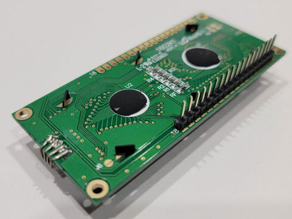
This image shows a standard 16x2 character LCD, often found in DIY projects.
Character Liquid Crystal Displays (LCDs) are a fantastic addition to many electronics projects. These handy devices allow programmers to display status and debug messages for easier bug fixing, and they give users of a project a more intuitive way to interact with the device. There’s a good chance that you’ve already used a library that allows you to effortlessly incorporate such a display into one of your Arduino or Raspberry Pi projects!
Looking at the underlying communication protocol implemented by these libraries uncovers a few exciting possibilities. Furthermore, understanding the nitty-gritty details of these displays allows you to utilize simple character LCDs in many new projects, even without adding an Arduino or a similar MCU development board. This article investigates the most commonly used communication protocol of a standard 16x2 character LCD and how you can use it in your projects.
The Hitachi HD44780 LCD Controller
Since its introduction in the 1980s, the HD44780 controller has become a de-facto standard for communicating with LCDs. Therefore, almost all character LCDs share the same 14 to 16 pins that you need to connect to utilize such a display in your project. You can find a detailed description of how to interface LCDs using an Arduino in this article.
 Manufacturers often hide the LCD controller under a blob of dark-gray resin, as shown in this image.
For now, focus on the RS (register select), EN (enable), and the eight data pins (D7 through D0) of the LCD. Note that there is also an RW (read/write) for selecting the direction of an operation. However, it doesn’t make sense to read data from the display in many cases. Therefore, this pin is often tied to GND to permanently make the display operate in write mode (for transmitting data from a controller to the LCD).
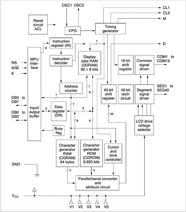
 This image shows the internal structure of the HD44780 LCD controller. The rather complicated-looking internals make it quite easy to interface an LCD using a simple external microcontroller. Image Source: https://www.sparkfun.com/datasheets/LCD/HD44780.pdf
When using the controller’s eight-bit mode, the MCU writes all eight data bits at once while keeping the RS and RW pins stable. The HD44780 latches the incoming data with the next falling edge it detects on the EN pin. In 4-bit mode, the HD44780 expects the MCU to send the most significant bits (B7-B4) first before transmitting the lower bits (B3-B0). Therefore, in 4-bit mode, the MCU needs to keep the RS and RW pins stable and use the EN pin to indicate that the next 4-bits are stable.
Additionally, the MCU can use the RS pin to select one of the two registers of the HD44780 it wants to access. Pulling the RS pin low selects the controller’s command register, for example, to clear the display. Setting the RS bit high, on the other hand, lets the MCU write data to the controller’s data register, for example, characters to display. Putting all this information together, we can derive the following table of supported bit combinations and what they mean:

In the table above, the lower-case x means that the bit in this position can be set to any value. Additionally, you can see that some commands take parameters that change their behavior. For example, the I/D bit indicates whether the controller should increment or decrement the cursor position. When the S bit of the same command is set, the controller shifts the display contents. Next, the D, C, and B bits control whether certain display functions are on or off. For example, using the D bit, you can turn off the entire display, the C bit lets you enable or disable the cursor, and B activates or deactivates the cursor blink. Similarly, S/C and R/L let you shift or move the display contents (S/C) in a specific direction (R/L). Lastly, the DL, N, and F bits allow you to set the display to operate in either 4-bit or 8-bit mode (DL), specify the number of display lines (N), and select the font (F).
Summary
Communicating with a standard 16x2 character LCD is not as difficult as it might seem at first. Each command that the HD44780 controller accepts consists of eight data bits. The standard HD44780 supports two communication modes. In eight-bit mode, the MCU that wants to display data needs to send all eight bits at once while keeping the RS and RW lines stable. The MCU can instruct the controller to latch all eight data bits using the EN line. However, the MCU needs to transmit the eight data bits using two half-bytes in four-bit mode. Similar to the eight-bit mode, the RS and RW lines must remain stable during the entire transmission. However, in four-bit mode, the MCU needs to send two EN pulses that signal the HD44780 to latch each of the four data bits.
The HD44780 contains two registers, and the MCU can select which one it wants to access using the RS bit. Setting this bit low selects the LCD controller’s command register, and pulling the pin high allows the MCU to access the HD44780’s data register. The controller supports eleven commands that may or may not allow the MCU to supply additional parameters by setting various bits.
Have questions or comments? Continue the conversation on TechForum, DigiKey's online community and technical resource.


