Zener Diode: Basic Operation and Applications
2015-12-16 | By Jia (Rabiyya Khan)
A Zener diode is a silicon semiconductor device that permits current to flow in either a forward or reverse direction. The diode consists of a special, heavily doped p-n junction, designed to conduct in the reverse direction when a certain specified voltage is reached.
The Zener diode has a well-defined reverse-breakdown voltage, at which it starts conducting current, and continues operating continuously in the reverse-bias mode without getting damaged. Additionally, the voltage drop across the diode remains constant over a wide range of voltages, a feature that makes Zener diodes suitable for use in voltage regulation.
Zener diode operation
The Zener diode operates just like the normal diode when in the forward-bias mode, and has a turn-on voltage of between 0.3 and 0.7 V. However, when connected in the reverse mode, which is usual in most of its applications, a small leakage current may flow. As the reverse voltage increases to the predetermined breakdown voltage (Vz), a current starts flowing through the diode. The current increases to a maximum, which is determined by the series resistor, after which it stabilizes and remains constant over a wide range of applied voltage.
Figure 1: Zener diode IV characteristics
Zener breakdown
The breakdown is either due to the Zener breakdown effect that occurs below 5.5 V, or impact ionization that occurs above 5.5 V. Both mechanisms result in the same behavior and do not require different circuitry; however, each mechanism has a different temperature coefficient.
The Zener effect has a negative temperature coefficient while the impact effect experiences a positive coefficient. The two temperature effects are almost equal at 5.5 V and cancel out each other to make the Zener diodes rated at around 5.5 V the most stable over a wide range of temperature conditions.
Zener diode specifications
Zener diodes vary in specifications such as nominal working voltage, power dissipation, maximum reverse current, and packaging. Some commonly used specifications include:
- Voltage Vz: The Zener voltage refers to the reverse breakdown voltage—2.4 V to about 200 V; can go up to 1 kV while the maximum for the surface-mounted device (SMD) is about 47 V).
- Current Iz (max.): Maximum current at the rated Zener voltage Vz—200 uA to 200 A).
- Current Iz (min.): Minimum current required for the diode to break down—5 mA and 10 mA.
- Power rating: The maximum power the Zener diode can dissipate; given by the product of voltage across the diode and the current flowing through. Typical values are 400 mW, 500 mW, 1 W, and 5 W; for surface mounted, 200 mW, 350 mW, 500 mW, and 1 W are typical.
- Voltage tolerance: Typically ±5%.
- Temperature stability: Diodes around 5 V have the best stability.
- Package: Leaded devices and the surface mount either as discrete devices or within integrated circuits.
- Zener resistance (Rz): The diode exhibits some resistance as evident from the IV characteristics.
Figure 2: Zener diode resistance
Zener diode applications
Zener diodes are used for voltage regulation, as reference elements, surge suppressors, and in switching applications and clipper circuits.
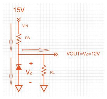
Voltage regulator
The load voltage equals breakdown voltage VZ of the diode. The series resistor limits the current through the diode and drops the excess voltage when the diode is conducting.
Figure 3: Zener diode shunt regulator
Zener diode in overvoltage protection
If the input voltage increases to a value higher than the Zener breakdown voltage, current flows through the diode and create a voltage drop across the resistor; this triggers the SCR and creates a short circuit to the ground. The short circuit opens up the fuse and disconnects the load from the supply.
Figure 4: SCR overvoltage crowbar circuit
Zener Diode Clipping Circuits
Zener diodes are used to modify or shape AC waveform clipping circuits. The clipping circuit limits or clips off parts of one or both of the half cycles of an AC waveform to shape the waveform or provide protection.
Figure 5: Zener diode clipping circuits
Recommended Reading
What is a Diode? – ATM | DigiKey
How To Calculate Capacitance in Series or Parallel – ATM Quick Take | DigiKey
Calculate PCB Trace Width – ATM Quick Take | DigiKey
What is the Difference in AC vs DC Current? – ATM Quick Take | DigiKey
How to Calculate Resistance in Series or Parallel – ATM Quick Take | DigiKey
Have questions or comments? Continue the conversation on TechForum, DigiKey's online community and technical resource.


