制造商零件编号 145334-1
SPUDGER 3-PACK
iFixit
Today we’re looking inside the Relief Band, a motion sickness wearable. It works by stimulating the nerve in your wrist that has been found to relieve motion sickness. You may have heard of or seen the compression-style wristbands before, but this takes it up a notch by using electricity to stimulate the nerve using two electrodes that you’re supposed to place on the inside of your wrist and turn it up until you can feel the buzz up through your first fingers. The single button on the device increases the power level when pressed, or turns the device off if you hold it down.
This “50 hours” version is great for keeping in the car in case I forget to take my Dramamine. I find the electrical stimulation a little annoying, so I don’t think I would want to rely on it for the whole car ride or whatever else is making me motion sick, but it is great for the 20 minutes it takes the Dramamine to kick in. Because if you get motion sickness, you know that once you’re queasy, nothing can make that feeling go away until you stop moving.
To take this gadget apart, I used leverage to pop the two halves of the enclosure apart. As I suspected, it is possible to replace the coin-cell batteries inside when they die, and then snap the enclosure back together. But I get it, they wanted to offer a more affordable SKU than their rechargeable models, some of which also have a screen.
Thanks to David Cranor for lending his EE expertise and to Lumafield for the 3D scan.

Tools used in this teardown:

Upon first inspection, the device appears quite straightforward. The parts that come into contact with your skin are pads for a large inductor. The outer metal bits are designed to attach to the watchband, simple-shaped pieces of metal.
Inside, we find two batteries with a small washer serving as a spacer between them. The device uses one CR2016 and one CR2025. This seems to be a cost-saving measure; both batteries offer the same voltage, but one has a smaller capacity than the other. Interestingly, if you were to replace the batteries, using two of the thicker ones without the washer, you would extend the device's lifespan beyond the usual 50 hours.
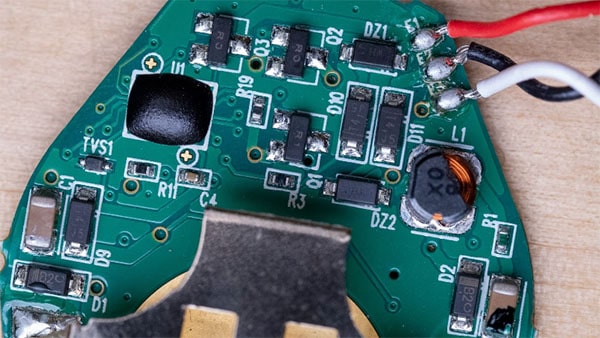
Further examination reveals a surprisingly simple circuit. There's a battery, power conditioning, a mechanism that generates zaps, a button, and some LEDs. The magic likely lies in the firmware they're using to generate the zaps, dictating factors such as frequency, voltage, and waveform shape.

Embedded in an epoxy blob, the device's microcontroller chip is a crucial part of its operation. The circuit board also hosts an inductor, the component that creates the zaps that the device emits to combat motion sickness.

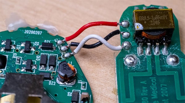
The big inductor is labeled 1.65 millihenrys (a unit of inductance). It has contacts that connect to what we like to call the 'zappy plates' aka electrodes. These plates come into contact with the user's skin, delivering the zaps generated by the device with the help of a conductive gel.

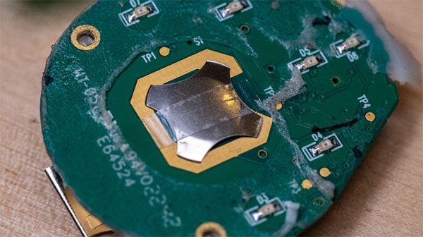
We identified the light-emitting diodes (LEDs) on the device, also a snap dome taped down onto the board. It's a button made out of a piece of sheet metal, which can be easily soldered or taped straight onto a circuit board.
The smaller inductor could be part of a boost or buck regulator, which helps regulate the voltage.
The device operates at 6 volts, with the two 3-volt batteries connected in series. It likely has a mechanism to switch the 6 volts down to a regulated 3.3 or 5-volt rail. This then powers up the much higher voltage zap mechanism.

Here are all the components we could identify:
We used my oscilloscope to take a closer look at the signals going to the electrodes.
The oscilloscope's readings helped us understand what we were feeling when we touched the electrical current. We also had a chance to look at the shape of the zap. It was fascinating to see how the oscilloscope visualized the electrical current - it could even be several zaps layered on top of each other.
We decided to increase the voltage to see what would happen. The oscilloscope can handle up to 150 volts, so we felt safe doing this. As we increased the voltage, we saw the same shape, but it was bigger.
You can explore the CT scan of the Relief Band on Lumafield.