What You Need to Know About Synchronous Voltage Regulation
投稿人:电子产品
2015-09-29
Switching DC-to-DC voltage converters (“switching regulators”) are popular because they generally exhibit high efficiency. However, the low-side diode used to complete the current path in an asynchronous switching regulator can compromise peak efficiency.
By replacing the diode with a metal-oxide semiconductor field-effect transistor (MOSFET) and synchronizing its operation with the power (“high-side”) MOSFET, efficiency can be improved but at a cost of added complexity.
This article reviews synchronous voltage regulation and describes some commercial modules that incorporate the technique.
Striving for efficiency
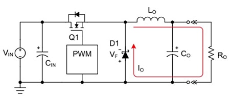
The basic principle of an asynchronous switching regulator (Figure 1) is simple. Pulse-width modulation (with a duty cycle proportional to the output voltage) at a set frequency is used to switch the high-side MOSFET. During the MOSFET’s ON cycle, a voltage equal to VIN - VOUT is induced across the inductor and the inductor current rises with a slope equal to (VIN - VOUT)/L.

Figure 1: Switching power supply using asynchronous regulation. (Courtesy of Fairchild Semiconductor)
When the high-side MOSFET switches OFF the current flowing through the inductor is disrupted. Without the diode (D1) there would be no return path for the current and it would build up across the inductor resulting in a large (and potentially damaging) voltage spike. With the diode present, during the OFF cycle the inductor voltage polarity reverses, forward biasing the diode and providing a path for the current to continue flowing around the circuit in the same direction as when the MOSFET was ON. (Such circuit operation is described as “freewheeling.”)
(Note that the polarity reversal of the inductor that forward biases the diode occurs naturally and requires no control circuitry. [See the TechZone article “The Difference Between Switching Regulator Continuous and Discontinuous Modes and Why It's Important.”])
Asynchronous regulators are relatively efficient devices. For example, Semtech’s SC4524C is an asynchronous buck-switching regulator with 3 to 28 V input and a maximum output of 27 V and 2 A. The claimed peak efficiency is 89 percent (VIN = 12 V, VOUT = 5 V, IOUT = 1A). However, the pressure to extend battery life (or offer more functionality in new generations of products without compromising battery life) has generated demand for switching regulators with even higher efficiency.
One drain on the performance of an asynchronous regulator is the low-side diode. The diode requires a forward-bias voltage before it will conduct. The forward-bias voltage causes the diode to dissipate power adversely affecting the efficiency of the switching regulator. The problem is worse at lower-duty cycles because the OFF cycle (when the circuit is freewheeling and the diode is dissipating power) is longer. (The requirement for a forward-bias voltage also means there must always be a finite difference between the input and output voltages of the switching regulator below which it “drops out.”)
The effect is also more significant at low loads––for example, the kind of loads that occur in “sleep” or “stand-by” modes to which portable products revert in order to save battery power –– because it remains constant while other losses diminish.
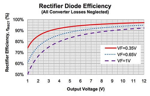
Diode manufacturers have improved the situation by offering products requiring lower forward bias voltages (Figure 2), but an even better solution is to replace the diode with a second MOSFET.

Figure 2: Reducing the diode forward voltage in an asynchronous switching regulator improves efficiency. (Courtesy of Fairchild Semiconductor)
Figure 3 shows a schematic of a switching regulator with a second MOSFET. The operation of the two MOSFETs is synchronized with one switching ON while the other switches OFF. For this reason this type of power supply is known as a synchronous switching regulator.

Figure 3: In a synchronous switching regulator the diode is replaced with a second MOSFET. (Courtesy of Fairchild Semiconductor)
Comparing topologies
In a synchronous design the low-side MOSFET that replaces the diode has a much lower (drain-to- source) resistance, reducing the power dissipated across the component and improving the overall efficiency.
Another advantage is that the second MOSFET is typically integrated into the module eliminating an external component (the diode) and shrinking the regulator’s footprint. However, integrating the MOSFET does increase the heat generated by the package so additional thermal management is needed.
Another downside of synchronous operation is that it requires control circuitry in the power module IC, increasing complexity, size, and cost. Precise synchronization is required to ensure there is no overlap in the MOSFETs’ switching which otherwise would cause a short to ground and catastrophic failure. (Asynchronous topologies face no such risk.)
There are many examples of synchronous switching regulators on the market. For example, Semtech’s SC195 is a 500 mA synchronous regulator with an input voltage range of 2.9 to 5.5 V and an output of 0.8 to 3.3 V. The regulator operates at a fixed frequency of 350 MHz with a claimed efficiency of up to 94 percent (VIN = 4 V, VOUT = 3.3 V, IOUT = 10 mA).
Texas Instruments (TI) offers the LM5175, a synchronous four-switch step-up/step-down (“buck”/”boost”) switching regulator which operates over an input-voltage range of 3.5 to 42 V and provides a 0.8 to 55 V output. The module integrates two MOSFET gate drivers capable of handling up to 2 A. The claimed efficiency is around 97 percent (VIN = 24 V, VOUT = 12 V, IOUT = 5 A).
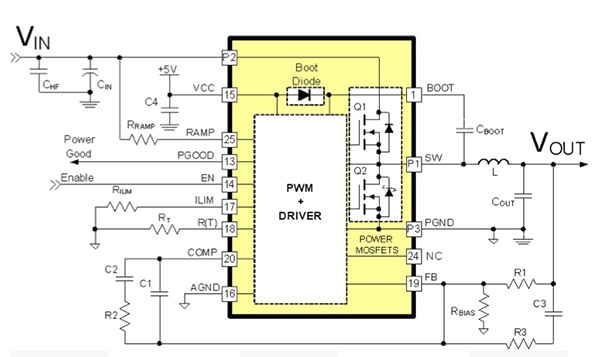
For its part, Fairchild Semiconductor offers the FAN2106 which features an input range of 3 to 24 V and an output range of 0.8 to 80 percent of VIN. The device integrates both MOSFETs and the controller/driver circuitry into a single module (Figure 4) to produce a synchronous switching regulator with up to 6 A output and 95 percent efficiency (VIN = 8 V, VOUT = 3.3 V, IOUT = 2 A).

Figure 4: Fairchild’s FAN2106 integrates two MOSFETs and controller/driver circuitry into a single module.
For more information about the parts discussed in this article, use the links provided to access product pages on the DigiKey website.
Additional Reading
- “Synchronous vs. Asynchronous Buck Regulators,” Ajith Jain, Director Strategic Marketing, Power Management, Semtech Corporation
- “Synchronous Rectification for Forward Converters,” Steve Mappus, Fairchild Semiconductor
免责声明:各个作者和/或论坛参与者在本网站发表的观点、看法和意见不代表 DigiKey 的观点、看法和意见,也不代表 DigiKey 官方政策。


 中国
中国