Vehicle-to-Grid Gains Traction as Elastic Energy Reservoir
投稿人:电子产品
2015-09-30
Connected to the grid, high-capacity battery stacks in electric vehicles and homes provide an elastic energy reservoir able to expand and contract as needed to serve the power grid. Using grid-connected bi-directional converters, these battery stacks can help balance periods of high-demand peaks and low-demand valleys on the grid. Designing a suitable converter can be challenging but engineers can take advantage of devices designed for high-efficiency power conversion from multiple vendors including Diodes Incorporated, Fairchild Semiconductor, International Rectifier, Intersil, Linear Technology, Maxim Integrated, Microchip Technology, ON Semiconductor, STMicroelectronics, and Texas Instruments, among others.
The concept of vehicle-to-grid (V2G) or home-to-grid (H2G) power has emerged from growing recognition of the ability of large-scale recruitment of small energy stores to meet growing challenges associated with highly variable power demand. At the macro level, the V2G and H2G concept envisions many EVs (or home battery stacks) charging at night when power demand is low — so-called “valley filling” — and returning power to the grid when demand is high (“peak shaving”). Although the concepts can apply to H2G as well, attention has focused primarily on V2G, given the increasing availability of electric vehicles (EVs) and plug-in hybrid EVs (PHEVs). Indeed, EVs and PHEVs provide a substantial energy-storage capability in their own right. A typical battery system in an electric vehicle or plug-in hybrid EV can provide at least 10 kW of power, so a fleet of PHEVs can offer a substantial energy reservoir in aggregate.
Deploying V2G
In practical terms, however, V2G has found limited acceptance to date due to economic, technical, and consumer concerns. Success of this approach largely relies on a combination of favorable tariff structures and availability of a critical mass of connected EVs — none of which are immediately available. On the technical side, battery wear remains a concern: continual charging and discharging can reduce capacity and enhance wear with currently available battery technologies. Finally, consumers remain concerned about fair financial incentives from the utility, the health of their vehicle batteries, and whether the vehicles will have sufficient charge when actually needed for transportation. As industry addresses the economic and technical limitations, however, these pivotal consumer concerns stand to lessen. In fact, more advanced charging/discharging algorithms are already demonstrating reduced impact on the lifetime of large battery stacks.
Despite concerns about present economic and technical factors, V2G is already forming the basis of more flexible power-distribution strategies. For example, in what is being called the world’s largest V2G project, the US Department of Defense is employing a fleet of 42 V2G-capable EVs in a demonstration at the Los Angeles Air Force Base. The fleet includes both electric and hybrid vehicles, ranging from sedans to trucks and a 12-passenger van, and is seen as a testbed for the DoD’s focus on energy security, energy supply assurance, energy resiliency, and energy-demand reduction.
Although the US Air Force V2G project revolves around the notion of energy security and a self-sustaining microgrid, China has bigger plans for V2G. In its “China 2050 High-Renewable Energy Penetration Scenario and Roadmap Study”1 V2G technology is seen as the answer to a growing reliance on variable power sources (Figure 1).

Figure 1: A study of renewable energy’s contribution to China’s total power generation notes a growing reliance on variable power sources such as solar and wind and calls for deployment of V2G technologies to balance supply and demand. (Courtesy of the Energy Foundation China)
According to the study, the contribution of renewable power to the country’s total power generation will rise from a current level of 46 percent to 85 percent by 2050. At the same time, the contribution of variable power sources will rise from 30 percent to 60 percent, putting severe pressure on power utilities’ ability to maintain the real-time balance between electricity supply and demand. With a sufficient share of EVs among the millions of vehicles in Beijing alone, the Chinese see V2G technology able to stabilize Beijing’s grid against highly variable energy sources.
Key enabler
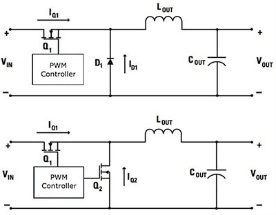
The key technical enabler for V2G/H2G deployment is the basic converter. Built with passive components, a typical buck or boost converter is designed to move power only from the input to the output. By replacing the traditional diode components with active switches, however, traditional converter topologies can move power in both directions (Figure 2). These bi-directional converters already find application in energy-harvesting applications such as regenerative braking, by building a converter based on this synchronous rectification approach.

Figure 2: A traditional switching buck converter (top) provides power from input to output but by replacing the traditional diode with an active switch (bottom); the resulting synchronous converter provides bi-directional power flow. (Courtesy of Texas Instruments)
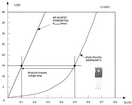
Used in this manner, an active switch such as a MOSFET provides nearly linear resistance and a lower forward-voltage drop compared to the traditional Schottky diode (Figure 3). As power supply designers have found, MOSFETs offer additional advantages, including the ability to operate in parallel to reduce the danger of thermal runaway in high-power applications. MOSFETs have a positive temperature coefficient, so when operating in parallel, MOSFETs exhibit an increase in resistance (and consequent reduced current flow) in the hotter device, shifting power flows to the cooler device. In contrast, Schottkys have a negative temperature coefficient, so increasing heat results in increased current flow in the hotter device — and increased chance of thermal runaway.

Figure 3: MOSFETs provide lower forward-voltage drop compared to Schottky diodes, resulting in improved converter efficiencies. For this example, comparing a 30 V MOSFET and 35 V Schottky diode at a forward current of 15 A, the conduction loss of the Fairchild FDMS8670S MOSFET is 1.5 W compared to 7.5 W for the Fairchild MBR4035PT Schottky. (Courtesy of Fairchild Semiconductor)
Even with their advantages, however, designers need to take special care in applying MOSFETs to synchronous-converter designs. The MOSFET body diode can exhibit very-slow reverse recovery with a substantial reverse-recovery current, compromising converter performance. The use of a parallel Schottky rectifier can help reduce this body-diode current in some scenarios. In fact, MOSFET families such as the Fairchild SyncFET family specifically designed for synchronous-rectification applications combine a PowerTrench MOSFET and parallel Schottky rectifier in a single package.
MOSFET body-diode reverse-recovery current can also be reduced by cutting the switch’s dead time to zero. With zero dead time, no current would flow in the body diode, eliminating the reverse-recovery and body-diode conduction losses. As a result, to achieve maximum efficiency with MOSFETs in synchronous converters, engineers need to apply very strict gating control.
Timing and performance
Indeed, because synchronous rectifier MOSFETs are active devices, their ability to outperform a Schottky diode rectifier critically depends on the gate-driving method and timing used to drive the synchronous rectification (SR) MOSFET (Q2 in Figure 2, bottom). A suitable timing design needs to ensure that Q1 and Q2 are never in active conduction mode at the same time. In addition, the dead time between Q1 and Q2 needs to be minimized to reduce frequency-related power losses associated with SR MOSFET body-diode conduction and reverse-recovery time.
To address these challenges, synchronous-converter designers typically rely on complex control schemes implemented in advanced-synchronous rectification controllers and processor-controller pulse-width modulation (PWM) devices. In a typical design, the controller switches MOSFET gate drivers, which in turn control the power MOSFETs. Gate drivers such as the Diodes Incorporated ZXGD3104N8, International Rectifier CHL8510, and Linear Technology LTC4449, are some examples of these. In fact, the Texas Instruments TPS28225 implements adaptive dead-time control without the need for additional control circuitry. Here, the TPS28225 senses the output of the driver going low and does not allow the gate-drive output of the other driver to go high until the first driver output falls below the specified threshold.
Complex timing schemes
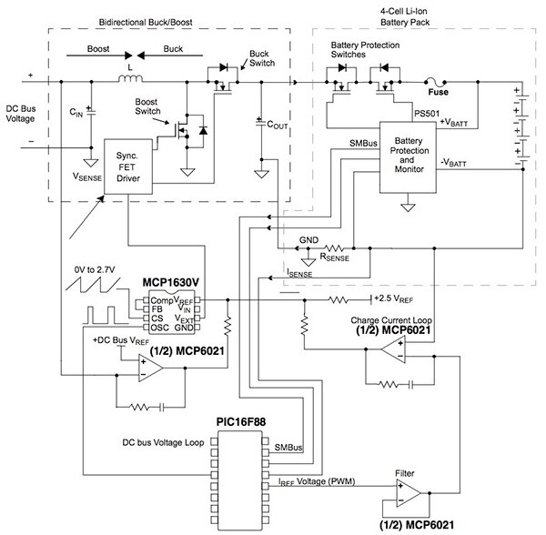
For implementing more complex control schemes, designers can use PWM devices such as the Microchip MCP1630V controlled by an MCU, such as the Microchip PIC16F88, to provide the precise timing needed to maximize efficiency of a bi-directional converter (Figure 4). At the same time, the MCU is able to monitor voltage and current levels using sensing circuits built around op amps such as the Microchip MCP6021.

Figure 4: A bi-directional power converter relies on an adaptive PWM such as the Microchip MCP1630V controlled by an MCU such as the Microchip PIC16F88 to provide critical timing needed to manage current flows to or from the battery stack. This type of design can be scaled to enable bi-directional power flows between the grid and very-high capacity battery stacks. (Courtesy of Microchip Technology)
In some applications, engineers can turn to dedicated synchronous rectification controllers such as the Intersil ISL6545, Maxim Integrated MAX1771, and ON Semiconductor TL594, which provide an integrated control solution. Highly integrated MCUs can provide highly effective solutions with a minimum of additional components. MCUs such as the STMicroelectronics STM32F334 and Texas Instruments MSP430F67641 integrate analog-to-digital converters and PWMs, enabling implementation of a comprehensive solution designed to operate gate drivers in a synchronous-converter design (Figure 5).

Figure 5: Engineers can use integrated MCUs such as the STMicroelectronics STM32F334 to implement sophisticated control algorithms needed to maximize efficiency in a synchronous converter. (Courtesy of STMicroelectronics)
Summary
The promise of rapid expansion and contraction of grid capacity offers a compelling solution for managing high-variable energy sources such as solar and wind. By connecting the grid to mobile battery stacks found in EVs or stationary stacks found in energy-harvesting systems, the grid could use this distributed capacity to store excess energy when demand is low or draw on this capacity when demand is high. At the same time, a critical element in this vehicle- and home-to-grid concept is the availability of highly efficient bi-directional converters. Using available devices including MOSFETs, gate drivers, controllers, and MCUs, engineers can build sophisticated bi-directional converters capable of delivering on the vision of an elastic grid.
For more information on the parts discussed in this article, use the links provided to access product pages on the DigiKey website.
References
免责声明:各个作者和/或论坛参与者在本网站发表的观点、看法和意见不代表 DigiKey 的观点、看法和意见,也不代表 DigiKey 官方政策。


 中国
中国