Use Monolithic Universal Active Filter ICs to Speed IoT Analog Front-End Design
投稿人:DigiKey 北美编辑
2017-11-15
When designing for the IoT, it seems easy – just convert the sensor or RF signal to digital and work from there. But not so fast: it’s still an analog world and those inputs to analog-to-digital converters (ADCs) need to be band limited to prevent aliasing. Similarly, the outputs of digital-to-analog converters (DACs) need to be filtered to reduce harmonics and eliminate ‘spikes.’
However, while both time to market and analog expertise are increasingly limited, the design constraints in terms of filter types, roll-offs, reliability, and accuracy remain, and cannot be compromised.
To meet both the performance and design requirements, universal active filters are a good solution. These standard building blocks for analog filters offer flexible filter topologies, fast design cycles, and effective band limiting to solve myriad band limiting requirements.
This article will describe the need for active front-end filtering and its typical design requirements, constraints, and tradeoffs. It will then introduce three universal active filter types, their salient characteristics, and how to use them appropriately for best results.
Applying the filter
An anti-aliasing filter or a band reject filter should be installed between the sensor’s buffer amplifier and the ADC (Figure 1).

Figure 1: The filtering between the sensor and the ADC plays a critical part in the IoT to prevent aliasing and eliminate spurious signal pickup, thereby improving signal quality. (Image source: Digi-Key Electronics)
The filter must be placed before the sensor’s ADC to limit the bandwidth of the ADC input. Placing it after the sensor buffer minimizes any loading on the sensor due to the filter. In this location the filter can band limit the sensor output and eliminate spurious signals.
Aliasing
Digitizing an analog signal requires sampling it at a rate that is greater than two times the highest frequency component present in the signal in order to recover the signal without error. If the analog signal is sampled at less than twice its highest frequency, then spectral distortion in the form of aliasing occurs (Figure 2).

Figure 2: Viewing the sampling process in the frequency domain shows that sampling at less than twice the signal bandwidth results in spectral distortion due to aliasing. (Image source: Digi-Key Electronics)
Sampling is a mixing operation. In the frequency domain (right side of Figure 2), the baseband signal up to its bandwidth (fBW) is replicated as upper and lower sidebands about the sampling frequency and all of its harmonics. As long as the sampling frequency is greater than twice the signal bandwidth, the baseband spectrum and the lower sideband about the sampling frequency do not interact. If the sampling frequency is reduced to less than twice the signal bandwidth, then the baseband signal and the lower sideband about the sampling frequency interact, irretrievably distorting the signal.
In the context of digitizing an IoT sensor, the signal from the sensor needs to be band limited to less than half the sampling rate - called the Nyquist frequency. This is accomplished by filtering the sensor output signal. It may also require additional filtering to remove interfering signals.
Filter types
Filters are active or passive circuits that eliminate unwanted frequency components from a signal, enhance wanted signal components, or both. Filters are best described in the frequency domain (Figure 3).

Figure 3: The four basic filter types are low-pass, high-pass, band-pass, and band-stop filters. (Image source: Digi-Key Electronics)
A low-pass filter passes signals with frequencies lower than its bandwidth (fpass) and attenuates signals with frequencies greater than its bandwidth. Once the signal frequency exceeds the filter bandwidth, its amplitude is attenuated, usually proportional to frequency, until it reaches the stop-band (fstop) where the maximum attenuation is achieved. Variations in filter attenuation across the pass-band region are referred to as pass-band ripple. Similarly, variations in the stop-band signal levels are stop-band ripple. The region between the upper end of the pass-band and the lower stop-band limit is called the transition region.
High-pass filters, as the name implies, pass signals with frequencies above the lower pass-band limit (fpass) and attenuate signals with lower frequencies.
A pass-band filter passes signal frequencies between its pass-band limits (fpass1 and fpass2) and attenuates signals with frequencies outside that range.
A band-stop or band-reject filter attenuates signals within its stop-band and passes those within its pass-bands.
Low-pass filters are selected for anti-aliasing before an ADC and as reconstruction filters after a DAC.
Filter responses
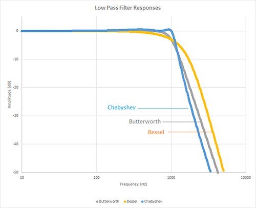
Designers can choose from multiple filter response types that control the pass-band ripple, the slope of the transition region, the stop-band attenuation, and the filter phase response. Common response types are Bessel, Butterworth, and Chebyshev (Figure 4).

Figure 4: Comparing the Bessel, Butterworth, and Chebyshev low-pass filter responses. (Image source: Digi-Key Electronics)
An ideal low-pass filter would provide infinite attenuation to eliminate signals above the cutoff frequency, and pass signals below the cutoff frequency with unity gain. In the real world, various trade-offs are required to optimize performance for each application.
The three filter responses shown in Figure 4 have specific characteristics. The Butterworth filter has a maximally flat amplitude response. This means it offers the flattest gain response in the pass-band with moderate roll-off in the transition region. This filter might be chosen if amplitude accuracy is the paramount concern.
Bessel filters offer maximally flat time delay for constant group delay. This means they have linear phase response with frequency and excellent transient response for a pulse input. This excellent phase response comes at the expense of flatness in the pass-band and a slower initial rate of attenuation beyond the pass band.
Chebyshev filters are designed to present a steeper roll-off in the transition region but have more ripple in the pass-band. It would be the filter of choice if the sampling rate was close to the signal bandwidth.
These characteristics can be readily observed in Figure 4.
Filter order
Filter order refers to the complexity of the filter design. The term relates to the number of reactive elements, such as capacitors, in the design. In general, the order of a filter affects the steepness of the transition region roll-off and hence the width of the transition region. A first-order filter has a roll-off of 6 dB per octave, or 20 dB per decade. A filter of the nth order will have a roll-off rate of 6×n dB/octave or 20×n dB/decade. So a fourth-order filter has a roll-off rate of 24 dB per octave or 80 dB per decade.
The order of a filter can be increased by cascading multiple filter sections. For example, two second-order low-pass filters can be cascaded together to produce a fourth-order low-pass filter, and so on. The trade off in cascading multiple filters is an increase in cost and size as well as a decrease in accuracy.
Universal active filters
Continuous signal active filters are implemented using operational amplifiers with resistor/capacitor (RC) passive elements. Several integrated circuit suppliers offer universal active filters containing the op-amps and critical RC components to simplify filter design and fabrication.
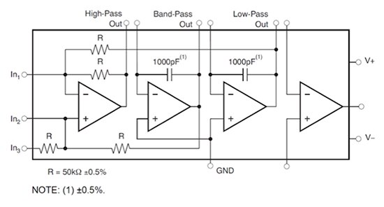
The first of these is the UAF42AU manufactured by Texas Instruments. This universal filter uses a classic state variable topology employing three operational amplifiers - two as integrators and a third as a summer. A fourth, uncommitted, op-amp is included to provide design flexibility (Figure 5). Each of these ICs offers a two-pole or second-order filter element with a maximum pass-band of 100 kHz.

Figure 5: The Texas Instruments UAF42AU universal active filter employs a state variable filter topology. (Image source: Texas Instruments)
The internal passive components in the UAF42AU have tight tolerances (0.5%) to ensure stable and repeatable performance.
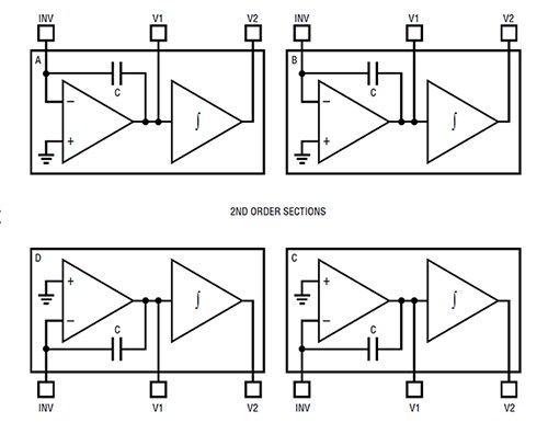
Another universal active filter by Linear Technology takes a slightly different approach. The LT1562 family includes four independent second-order filter blocks optimized for frequencies of from 10 Hz to 150 kHz (Figure 6).

Figure 6: The block diagram of the Linear Technology LT1562 quad universal filter showing four second-order sections. (Image source: Linear Technology)
This universal filter is intended for applications requiring high dynamic range where multiple second-order sections can be cascaded to achieve up to an eighth-order filter.
Maxim Integrated offers universal active filters with up to four second-order sections per device. The MAX274 includes four sections of second-order state variable filter blocks (Figure 7). The MAX274 offers a maximum bandwidth of 150 kHz. All four sections can be cascaded to create up to an eighth-order filter.

Figure 7: The block diagram shows a single section of a Maxim Integrated MAX274 quad continuous time active filter. (Image source: Maxim Integrated)
All of these universal filter integrated circuits can be configured with Butterworth, Bessel, or Chebyshev responses. Most can be designed as any of the common filter types: low-pass, high-pass, band-pass, or band-stop.
Design support
All of the universal active filter components discussed are supported by their manufacturers with a full complement of design aids to support rapid development, and production. These include application notes, filter design programs, and CAD and simulation models.
An example of this support is the design simulation of a 60 Hz notch filter, which is used to suppress power line crosstalk in a sensor (Figure 8).

Figure 8: The simulation of a 60 Hz band-stop or notch filter based on the Texas Instruments UAF42 active filter using the manufacturer supplied simulation model. (Image source: Digi-Key Electronics)
This design is based on the Texas Instruments UAF42 spice model and provides over 30 dB of attenuation at 60 Hz. In this case, Texas Instruments supplied the simulation program as well as the IC model.
Conclusion
Universal active filter building block ICs provide a fast and accurate method to design and build analog active filters, from the simplest to the most complicated, in a quick and simple way. They offer great flexibility in the choice of filter types, responses, and topology to match any application need.

免责声明:各个作者和/或论坛参与者在本网站发表的观点、看法和意见不代表 DigiKey 的观点、看法和意见,也不代表 DigiKey 官方政策。


 中国
中国