Understanding and Implementing MIMO RF Links
投稿人:电子产品
2014-01-09
After many years as a theoretical approach and academic topic, multiple-input multiple-output (MIMO) transceiver systems are receiving significant design-in attention and support components. The technology has been adopted for some of the latest 4G-generation and next-generation LTE (Long Term Evolution) cellular standards, to provide the throughput and performance needed, as well as in the Wi-Fi IEEE 802.11n standard.
The principle behind the MIMO approach is to use multiple, semi-independent antennas and transmit/receive channels at the base station and even the user handset, to overcome unavoidable signal-path problems such as noise, fading, and multipath. In effect, MIMO does a "ju-jitsu" flip on these problems; it applies advanced hardware and software to convert them from what were previously considered wireless weaknesses into significant strengths and advantages.
MIMO versus diversity systems
MIMO is much more sophisticated and complex than diversity antenna systems. Using multiple antennas for better signal coverage is a well-established technique; usually this is done at the receiver but it can also be done at the transmitter, which may not be co-located. (Note that to avoid confusion, the industry is now referring to basic single-antenna systems as single input, single output, or SISO.)
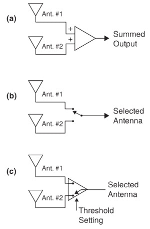
In a basic antenna diversity-receiver design, two or more antennas are used, spaced at least one-quarter wavelength apart. Each antenna's signal goes to an RF low-noise amplifier (LNA), and then the signals are combined. This combining can be done is different ways, with an increasing scale in complexity, cost, and benefit.
In the simplest approach (Figure 1a), the two (or more) amplified antenna signals are added or combined. The idea is that one antenna may be in a local "dead zone" but the other antenna will provide sufficient signal. Alternatively, if the problem is low SNR rather than low received power, the signal portion of the received energy will add linearly, but the random noise from the multiple antennas will add only by their root mean square (RMS) values, so there will be a net increase in SNR.
In the selection version of antenna diversity (Figure 1b), the SNR at each antenna is continuously measured and the system selects the antenna output with the best SNR, while blocking the others from reaching the receiver. Finally, in the switching diversity approach (Figure 1c), one antenna is used until its SNR falls below some pre-set threshold, then the system switches to an alternate antenna.

While diversity is an effective and relatively low-cost way of improving system performance, it has limitations in what it can achieve. In contrast, MIMO requires much more circuitry and embedded software (and signal-analysis and -processing algorithms) but can yield much better performance and consistency.
MIMO architecture and complexity
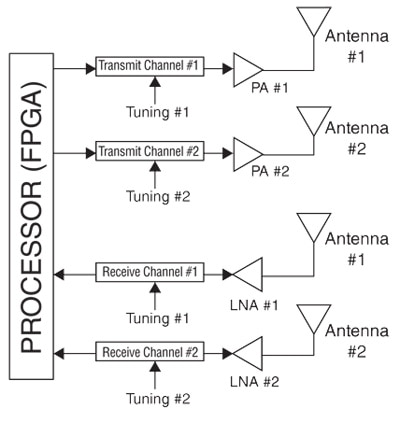
Rather than just rely on multiplicity of the antenna as in a diversity design, a MIMO system uses multiple antennas, receiver front-ends, and transmit paths. This creates multiple complete receive/transmit paths between antenna and system processor. The processor then has the task of managing these multiple paths for best system performance. A basic MIMO system with two channels each for transmit and receive paths is called a 2 × 2 design (Figure 2); some advanced base stations use up to eight channels each, given an 8 × 8 designation. Note that MIMO does not have to be symmetrical. It is possible to have a system with two transmit channels and one receive channel (a 2 × 1 designation), for example.

Of course, the above is a simplification of the reality of implementing a full MIMO architecture. The complete MIMO design has three major blocks: precoding, spatial multiplexing, and diversity coding:
In basic "single-layer" precoding, each transmit antenna broadcasts the same signal, but with phase and gain pre-adjustments to compensate for path delays, multipath, and other artifacts, with the goal of maximizing useful signal power at the receiver. Since a MIMO system has multiple receive antennas, the pre-coded data is split into several streams for the different antennas.
Spatial multiplexing uses the fact that there is more than a single transmit antenna. The high-rate signal is divided into multiple lower-rate signal streams, and each is transmitted by a different antenna but in the same frequency channel. Each of the multiple receiver antennas sees a different spatial signature; therefore the receiver can separate these streams into parallel channels.
Diversity coding takes advantage of the fact that fading characteristics for multiple antenna paths are usually independent, at least to some extent. It is used with a single stream rather than multiple streams, and the signal is coded with space-time coding, using full or near-orthogonal coding techniques such as OFDMA (Orthogonal Frequency Division Multiple Access), supporting both spatial multiplexing and diversity coding.
Because each antenna is independent and individually controllable as to signal phase, MIMO systems can be used for beamforming, where the aggregate antenna pattern is dynamically shifted to yield maximum performance at one or more of the receiver antennas (for example, to select a non-fading path). Similarly, the receiver antenna array can be beam-formed to focus on the signal coming from a direction that has better SNR and lower distortion or fading.
MIMO requires significant hardware
Compared to a SISO or diversity-antenna system, MIMO is both hardware and software intensive. Certainly, it needs complex, sophisticated algorithms to manage and dynamically adapt the data streams with encoding and decoding for multiple parallel channels. This requires a relatively-powerful processor, usually implemented as an FPGA.
MIMO also places major demands on the analog and mixed-signal hardware. It requires fully-independent, multiple channels for the receive chain from antenna through A/D converter, and for the transmit path from the D/A converter to antenna.
What makes MIMO possible at reasonable cost, with modest footprint and consuming low power is the availability of highly-integrated, application-optimized ICs. The AD9361 from Analog Devices (Figure 3) is a wideband 2 × 2 transceiver with "on-the-fly" user-programmability of key parameters. It combines an RF front-end with a flexible mixed-signal baseband section (with 12-bit ADCs and DACs) and integrated frequency synthesizers, simplifying design-in by providing a configurable digital interface to a processor. It operates from 70 MHz to 6.0 GHz, with tunable bandwidth from 200 kHz to 56 MHz.

Another MIMO-focused IC is the MAX2839 from Maxim Integrated Products (Figure 4), a direct-conversion, zero-IF, baseband-to-RF transceiver for 802.16e MIMO mobile WiMAX applications in the 2.3 to 2.7 GHz band. Its dual receivers have inter-channel isolation better than 40 dB, and it also includes a single transmitter channel. Among its other functional blocks are a VCO, frequency synthesizer, crystal oscillator, and baseband/control interface. It requires user-supplied RF bandpass filter, crystal, RF switch, PA, antenna, and a few passive components.

In addition to ICs such as these, a MIMO design's RF channels require multiple receiver LNAs, transmitter power amplifiers (PAs), and their associated control circuitry, plus multiple antennas. At present, these are not available in multichannel units, but only in single-channel/per package formats (except for some niche applications). However, the packages of these relatively simple devices are tiny and even chip-scale, so the real-estate footprint penalty is quite modest, while sensitive, low- and higher-power RF-signal routing is eased, since they can be placed close to their respective antennas.
Summary
MIMO architectures use a combination of multiple channels, signal-processing algorithms, and antennas to achieve higher throughput, lower BER, and better use of available RF spectrum. While it was considered impractical for many years, recent advances in ICs and processors have made it not only possible, but an accepted standard for Wi-Fi and other commercial applications. This article has reviewed the basics of MIMO, compared it to diversity antenna designs, and highlighted some MIMO-specific components that are available to implement it. More information on the parts mentioned here can be found by using the links provided to access product information pages on the DigiKey website.
免责声明:各个作者和/或论坛参与者在本网站发表的观点、看法和意见不代表 DigiKey 的观点、看法和意见,也不代表 DigiKey 官方政策。


