The Right DAC Can Simplify Your Next 5G or LTE MIMO Design
投稿人:DigiKey 北美编辑
2016-08-11
Space diversity using multiple input, multiple output (MIMO) transmit and receive antenna schemes really took off with IEEE 802.11a (5 GHz Wi-Fi), but as it now becomes increasingly important for LTE and 5G wireless, designers need to look closely at how it works, and the critical role digital-to-analog converters (DACs) play in realizing the optimum design.
Designers of wireless communication links usually face a challenge in meeting the project's multiple objectives. First, they must achieve a minimum bit error rate (BER). At the same time, they must strive to minimize power and also conserve bandwidth. Of course, these goals are somewhat in conflict: the easiest way to improve BER is to boost power, since doing so increases the signal-to-noise ratio (SNR); also, using more bandwidth is often a way to improve BER.
At the system level, the goal of improving performance and meeting these goals usually starts with a sophisticated data-encoding scheme that compresses the bit stream and also adds error detection and correction. However, once this data manipulation is completed, the burden of meeting the link goals falls on the transmit-side amplifier and antenna, and the receive-side antenna and front end.
To improve performance, engineers take advantage of one or more of three diversity techniques:
- Time diversity: in its simplest terms, this means repeating the message several times, including interleaving it, as shown in Figure 1.

Figure 1: In time diversity, the message is repeated one or more times to overcome noise in the channel, as a form of redundancy; it is often interleaved with other messages. (Image courtesy of Sahar Foroughi Farsani, Azad University of Najafabad, via Slideshare.net)
- Frequency diversity: using more bandwidth or channels, including frequency hopping and spread-spectrum techniques, which can overcome noise in parts of the spectrum; see Figure 2.
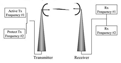
Figure 2: In frequency diversity, the message is transmitted on two or more channels, either simultaneously or in succession, to avoid noise in the spectrum. (Image courtesy of Telekomunikasi Dasar, via Slideshare.net)
- Space diversity: using two or more antennas, at the transmit side, or the receive side, or at both, to provide more physical paths for the wireless link; see Figure 3.
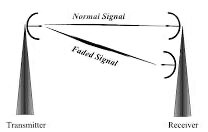
Figure 3: In space diversity, the message is transmitted on two or more physical paths, to improve performance versus local noise, as well as avoid physical obstacles. (Image courtesy of Telekomunikasi Dasar, via Slideshare.net)
While the first two techniques have been widely used for many years, space diversity lagged for technical reasons. Recently, however, it has been getting considerable attention: it is already used by LTE devices, and is part of the 5G wireless standard MIMO (multiple input/multiple output) space diversity for wireless handsets and mesh networks; see Figure 4.
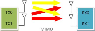
Figure 4: In a basic MIMO system, multiple antennas are used at both the transmit and receive ends of the data link; here shown with two antennas at each end. (Image courtesy of Telecomhall.com)
Note that MIMO topologies do not have to be symmetrical, and are classified by the number of transmit and receive antennas: a 3 × 3 MIMO has three of each, while a 3 × 2 version has three transmitter antennas and two receiver antennas.
A nomenclature note: it's perhaps somewhat counterintuitive, but the "output" term in MIMO does not refer to transmitter output; instead, it refers to the outputs from the receiver front end to the signal chain, so it’s the output of the link. Similarly, the "input" refers to inputs to the transmitter PA and to the radio link, not the inputs to the receiver.
MIMO basics
MIMO is a technique for improving link performance (improved SNR, reduced power requirements) between two points. Using MIMO and space diversity offer several advantages:
- By controlling the relative signal timing (phase shifting) of signals sent to each of the multiple antennas or received by each antenna, the link can produce static beamforming and even dynamic beamsteering. (Phase shifting uses principles of constructive and destructive interference between multiple wavefronts to direct energy in a desired direction.) This beamsteering allows a transmitter to focus on a desired receiver (via transmitter beamsteering) or a receiver to focus on a desired receiver (via receiver beamsteering), thus potentially minimizing the effects of interference, noise sources, and physical obstacles.
- Even if interference is not a concern, beamforming allows the transmitter to target the receiver (and vice versa) and so use less transmit power, while still delivering sufficient power to the intended receiver; it can mitigate the negative effects of link multipath.
- MIMO also improves overall system-wide performance of other channels and links since it reduces unnecessary RF energy in zones where it is not needed.
If MIMO is such a good idea, why hasn't it been used more often? A basic diversity-antenna arrangement has been used in consumer products such as wireless Wi-Fi routers to improve performance and minimize RF dead spots; but mobile applications have additional considerations related to wavelength dimensions, circuit complexity, processing requirements, and cost.
For example, to be effective, the multiple antennas need to be spaced at least one-quarter wavelength apart (at 1 GHz, a wavelength is 30 cm, so λ/4 is about 7.5 cm). Therefore, at lower frequencies, MIMO is only practical for fixed (stationary) situations. However, the use of bands at 2.4 GHz, 5.4 GHz, and higher (5G goes into the tens of GHz) makes it practical for portable devices such as smartphones and smart devices such as mesh-network nodes as λ/4 decreases.
Also, MIMO requires more circuitry. On the transmit side, it needs additional PAs, couplers, and antennas; at the receive side, it also needs additional antennas, front-end couplers, and low-noise amplifiers (LNAs), although some MIMO designs use a single LNA, switched among antennas.
A third factor is that MIMO needs more processing horsepower at the transmitter to manage the multiple beams and antennas compared to non-MIMO, and it needs significantly more at the receiver to make sense of the jumble of received signals. This horsepower translates to higher power consumption.
Despite these factors, it’s noteworthy that variants of MIMO have been used successfully in non-5G/non-mesh applications such as long-distance atmospheric-radio links. It is also the basis of phased-array radar, where hundreds of antennas are carefully phase-controlled to electronically steer the radar. In this situation, the transmitter antenna and the receiver antennas are the same physical components, and are connected to a PA and an LNA via a transmit/receive switch.
MIMO can be simplified
MIMO does not have to be symmetrical, with an equal number of transmit and receive antennas. One specialized variation called SIMO – single input, multiple output – uses several receiver antennas, but only one antenna on the transmitter; see Figure 5. This finds use in cases where reception problems at the receiver due to its location or ambient RFI are expected.

Figure 5: Reduced-complexity variants of MIMO systems use a single antenna at the transmitter and multiple antennas at the receiver (SIMO); or multiple antennas at the transmitter and a single antenna at the receiver (MISO). (Source: Wikipedia)
Due to the inherent complexity of MIMO, some applications choose to use another simplified version known as MISO (multiple input, single output). This diversity topology has multiple antennas only at the transmitter, but not at the receiver. Doing this may seem to be no simpler than SIMO, but that is not the case. MISO actually reduces both the circuitry and processing burden of the MIMO topology by much more than a simplistic "one-half" and is far less complicated than SIMO.
Why the difference? It's due to the inherent nature of transmitting signals versus receiving them. From basic principles of signal theory, as well as actual practice, we know that it is easier to transmit a given signal than it is to receive it. The reason is that transmitting is a largely deterministic process, with a known signal in a known and fairly benign environment, with minimal noise and distortion issues.
In contrast, receiving is a difficult process. The receiver faces many challenges associated with capturing and making sense of a largely unknown signal in an unknown and even hostile RF environment. The received signal has many probable types of impairments: channel noise, jitter, distortion, fading, multipath, carrier tuning shift and even Doppler-based drift, and, of course a low signal level and poor SNR.
The MISO version of MIMO recognizes this difference in difficulty of implementation and so puts emphasis on a more sophisticated transmitter, but retains the single-antenna receiver. This gives the largest performance boost for the smallest additional investment in circuitry and signal processing. At the same time, if needed, a MISO approach can be upgraded to full MIMO without having to redesign the transmitter, so it can be considered as a step along the path from standard single-antenna designs to a full MIMO approach.
The right components make MISO and MIMO easier
Since MISO is an attractive subset of MIMO, and can also be used as part of a full-featured MIMO topology, vendors have introduced analog front end (AFE) ICs that can help implement it.
One of the many issues when building a MISO system is maintaining timing alignment and eliminating phase shift between the various channels (timing changes corresponds to phase shifts, and phase shifts produce changes in beam-steering pattern). Thus, it is critical to design the system to ensure consistent and equal time delays between processor and each of the multiple transmit DACs.
At an extreme, in high-performance phased-array radar systems, even the minute phase shifts between channels due to different temperature coefficients of the interconnecting RF cables, can severely degrade performance. This timing requirement is helped if critical components such as DACs have features to help meet it.
One example of a MISO/MIMO-friendly IC is the LTC2000A family of 16-/14-/11-bit, 2.5 Gsamples/s DACs (Figure 6). The single (1.25 Gsample/s mode) or dual (2.5 Gsample/s mode) synchronous LVDS interface of these DACs supports data rates of up to 1.25 Gbits/s, using a 625 MHz DDR data clock.
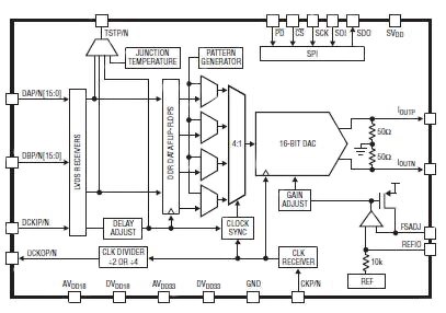
Figure 6: The LTC2000A family of 16-/14-/11-bit, 2.5 Gsample/s DACs from Linear Technology Corp. is well suited for MIMO and MISO designs, as it includes a register for correcting timing-alignment mismatches between the multiple transmit channels. (Image courtesy of Linear Technology)
To start, these DACs feature exceptional spectral purity, a "must have" for such designs. The devices feature:
- 80 dBc SFDR (spurious-free dynamic range) with a 70 MHz output frequency;
- SFDR than 68 dBc from DC to 1000 MHz;
- >78 dBc two-tone IMD (intermodulation distortion) from DC to 1000 MHz;
- Less than -165 dBc/Hz additive phase noise at 1 MHz offset for a 65 MHz output
All DACS in the family include an internal register that allows the system to adjust (fine-tune) data latency through the DAC. For the LTC2000A, the maximum timing-mismatch adjustment is 0.4 cycles of the sample-clock period, needed in multi-DAC designs (Figure 7).
Even if the design nominally meets the objective of matching channel-to-channel timing to within picoseconds, each DAC in the transmit path can then be fine-tuned to eliminate any residual mismatch or changes due to factors such as thermal drift.

Figure 7: The LTC2000A family is designed for MIMO and related systems, where a single FPGA drives multiple DACs and their transmit channels. (Image courtesy of Linear Technology)
Given the complexity of a GHz-rate MISO or MIMO design, an evaluation or demonstration board is important. LTC's DC2191A demonstration circuit supports the LTC2000 DAC, with the DAC driving their LT5579 up-converting mixer, see Figure 8. The circuitry on the DAC IF (intermediate frequency) output is optimized for analog frequencies ranging from DC to 500 MHz, while circuitry on the LO (local oscillator) input is optimized for frequencies from 1000 MHz to 4300 MHz, and the circuitry on the RF output is optimized for frequencies from 2200 MHz to 2600 MHz.
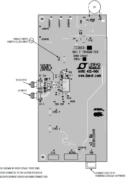
Figure 8: The DC2191A demonstration circuit exercises the LTC2000A DACs, and is used in conjunction with an Altera Stratix IV demo board; the demo circuit also includes an LT5579 up-converting mixer to generate the output RF signal. (Image courtesy of Linear Technology)
An Altera Stratix IV demo board is used to supply data to the DC2191, and the pair of boards is connected to a PC via a USB port. Along with LTC-supplied demo software, the demonstration set-up can be used for creating of complex waveforms, then loading them into the FPGA to test the DC2191 and the DAC using the PC as controller (Figure 9).
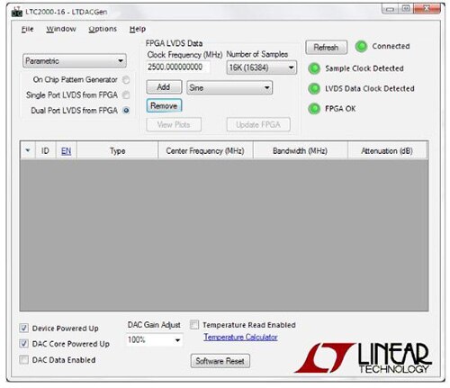
Figure 9: The software supplied with the DC2191A demonstration lets users create complex waveforms via a USB-connected PC, then load them into the FPGA to test the DC2191 and the LTC2000 DAC. (Image courtesy of Linear Technology)
Conclusion
Providing ever-higher data rates and reliable transmission, and doing so at higher frequencies, is an increasing and difficult challenge. To succeed, designers employ time, frequency, and space diversity techniques. The latter topology, often called MIMO, for multiple input, multiple output, has been used in larger, fixed installations, as well as 5 GHz Wi-Fi, but is now getting more attention as part of mobile LTE and 5G handsets, as well as mesh-network designs.
In a typical implementation, multiple antennas are used at the transmitter or receiver, or on both ends of the data link. While MIMO and simpler variants of antenna diversity provide improved SNR, BER, and dynamic beamforming, the design of MIMO systems requires close attention to signal timing along the multiple transmit channels, so it helps to identify the specialized DACs that have architecture and internal features optimized for the MIMO transmitter.

免责声明:各个作者和/或论坛参与者在本网站发表的观点、看法和意见不代表 DigiKey 的观点、看法和意见,也不代表 DigiKey 官方政策。


 中国
中国