The Heat is On: Using RF to Heat and Weld
投稿人:电子产品
2015-06-18
While most of us conjure up images of radios, data links, and communications when we think of RF, there is an entire subculture of RF design engineers whose work has nothing to do with communications. Instead, these engineers use RF to heat, weld, and seal metallic objects. An example we may be familiar with is inductive stove tops that heat metallic pots and pans while the surface remains cool.
Electromagnetic induction uses an induction coil that is driven with RF that causes a resistive heating effect from eddy currents induced in the metals in close proximity to the RF field. The metals, called susceptors, absorb this heat and can thermally conduct it into a larger area or volume (for applications like heating liquids), or cause melting, fusing, or welding very efficiently. There are no explosive gases, fumes, or chemicals, making this process ideal for factories and automated machinery lines.
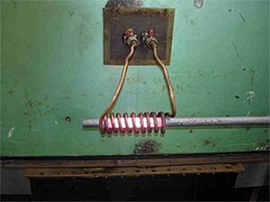
Figure 1: A 25 mm metal bar can be made red hot using 15 kW of RF energy at 450 kHz.
This article looks at inductive heating using RF energy and discusses design solutions and applications where this technology can be used. All parts, data sheets, tutorials, and development kits referenced here can be found online at DigiKey’s website.
Not just for cooking
For decades, inductive heating has been used on factory floors for sealing and packaging of metal containers. Early patent drawings show how relatively few components can implement an effective solution (Figure 2). Comparatively speaking, it is only fairly recently that inductive heating for cooking has been offered on medium- to low-cost cooking surfaces. However, we all have used products that have been inductively heat sealed. We are all familiar with cans of food that require an opener to break the vacuum seal. If you look carefully at the tops of these cans, you will see that the lids are welded to the cans; dedicated machines use specially designed inductive heaters driven by high-power RF to fuse the lids to the cans quickly, reliably, and repeatedly.
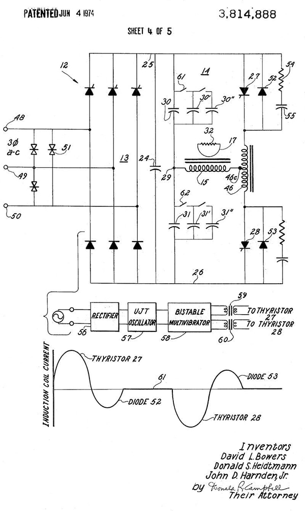
Figure 2: This early patent drawing shows how relatively few components are needed to make inductive welding and heating systems. The most demanding part of the design is the composition and dimensions of the RF transfer coil.
One can even find simple, free, and public-domain DIY designs available for education and hobbyist use. A simplified schematic (Figure 3, left) for a well-documented design (Figure 3, right) shows a relatively safe ceramic-protected field heater that you can build1.
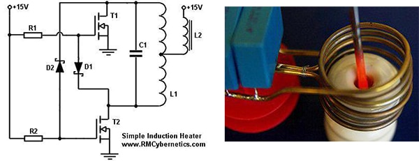
Figure 3: Educational kits and schematics are readily available online that can get you started with your own induction heating designs. A simplified schematic (left) for a well-documented design (right) shows a relatively safe ceramic-protected field heater that you can build.
Inductive heating is not just for use in metallic welding. It can also be used to harden or strengthen metals through annealing or to heat gases into plasmas for advanced chemical reactions and research. In all cases, high-power RF fields are needed and these designs encompass specialized discrete, as well as active, components. Even connectors must be carefully scrutinized to make sure they are passing the energy, not absorbing it.
Designing high-power RF for induction heating
Basic active and passive components for RF induction heating need to be able to handle large amounts of power, and they must be heatsinked to thermally conductive surfaces. Liquid cooling may be required as well, meaning that even the component’s housing and body may need to be thermally conductive to a high degree. A short 1,000 A current burst, for example, even through a 0.01 Ohm resistance will need to dissipate 10,000 W of power while the current is flowing.
Several suitable resistor manufacturers such as AVX, Bourns, and TE Connectivity offer fairly good high-power and well heatsinked resistors. These will typically be used in a chassis-mount configuration to allow thermal venting and transfer.
For example, take a look at the Bourns 50 Ohm chassis-mount CHF190104CBF500L 800 W resistor (Figure 4). Fifty Ohms is a magic sweet spot for RF matching and efficient power transfer and use, and both transmission lines and antennas are mostly made to match up to a 50 Ohm impedance.

Figure 4: The 50 Ohm chassis-mount resistor for 800 W designs allows maximum power transfer for the RF-transmission-line characteristics.
As part of the supplier’s CHF RF Power series, it is characterized from 0 to 1 GHz operations with a very-low (1.2) Voltage Standing Wave Ratio (VSWR) to minimize reflected signals and unnecessary heating.
Other values such as 12.5, 25 and 100 Ohms are available. Note how the selected values can be put in series and paralleled to create even higher power levels while distributing heat. A 1000 W version, the Bourns CHF190104KBF500L, is also available
High-power RF capacitors are not as common as resistors, transistors, and inductors, especially when it comes to RF-induction technologies. In most cases, series’ed and paralleled arrays may need to be made specifically for a design.
Important here is keeping equivalent series resistance and equivalent series inductance low. With potentially high levels of current, IIR heating is a concern, and even fairly high-temperature ceramic capacitors can degrade rapidly.
You do not want to use electrolytic or tantalum capacitors for these applications. Both types do not like overstresses and can actually explode violently during catastrophic failure. High-voltage versions of ceramic capacitors may be best to use, even if voltages are not that high. With inductive loading, very-high-level spikes and surges can arc across the tightly spaced ceramic capacitors. Older, high-voltage Mylar capacitors and polystyrene can provide good aging characteristics and tight tolerances, and can help eliminate arcing since these technologies are larger than the surface-mount ceramics.
Making the connection
Connectors can be of critical importance when designing high-power RF links that are designed to heat metals. After all, connectors use metals, leaving us with a conundrum: metal makes a good shield and RF connectors such as BNC, F type, MCX, SMA, and others use metal housings as part of the impedance control with the benefit of shielding.
However, these relatively small-sized connectors do not have much overall surface area and heat dissipation can be an issue. This means that when high-power links are needed, small and low-cost connectors are not suitable.
Once you do the engineering, you can make your own solids that are of the right composition, shape, and density for effective coupling. For mid-power, pre-final amplification stages, older style and larger RF connectors, such as the older UHF and N type, may be best.
Chassis-mount parts like the Cinch 26-8011 have a lot of thermal mass and make a good thermal connection to a solid chassis and/or heatsink (Figure 5). They are characterized at 50 Ohms and use reliable screw contacts instead of friction-dependent interlocking. This can make them safer in the presence of vibration and shock.
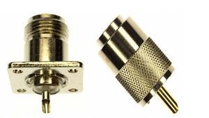
Figure 5: Impedance-controlled RF connectors with a lot of thermal mass that can efficiently transfer heat to a chassis or heatsink are useful for medium-power levels. Custom solutions may be required for very-high-power final stages after the final-power amplification.
Mating cables for RG-8, 213, 58, and 59, for example, use male plugs also with a lot of thermal mass. Brass and nickel coatings should be sufficient for most applications up to 500 MHz.
Power transistors
Very few tube designs are taking place and with high-voltage high-power semiconductor technology flourishing, many good semiconductor devices are ready to handle fairly good amounts of RF power.
While in most cases frequencies will not be that high, the current carrying capacity and voltages may be. For the most part, FET technology is best since it can carry with it very low RDS(on) specs while doing a good job of switching. Care must be taken to protect the FETs from overstresses since a thin oxide layer at the gate can rupture.
Parts like the NXP BLF578,112 are good choices here (Figure 6). This LDMOS RF FET can handle up to 88 A at up to 108 MHz and achieve a 1,000 W output level. Note the ceramic packaging with a large thermal volume and heatsink. Also available is the BLF178P,112, a dual version configured as a half bridge.
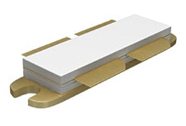
Figure 6: All high-power components may need heatsinking and cooling, but be careful: if the case and thermal mount are not electrically isolated, they may have different voltages and cannot mount to a common conductor.
Assessing your needs
Ultimately, it will be the types of materials that you want to weld or anneal that will determine the best frequency choices (or mixes of frequencies) for your needs. What’s more, it will be the volumes and cross-sectional areas you desire to heat or weld that will determine the power levels you will need.
In addition to cooking and welding, there are also less demanding uses of this technology. For example, a metallic weave may be used in a TFT display to allow precise and efficient heating control, allowing a display to operate at -50°C. As always, knowing the capabilities of RF technology and the parts you will need to implement for these and other applications is half the battle.
For more information about the parts discussed in this article, use the links provided to access product pages on the DigiKey website.
References
免责声明:各个作者和/或论坛参与者在本网站发表的观点、看法和意见不代表 DigiKey 的观点、看法和意见,也不代表 DigiKey 官方政策。


 中国
中国