Use A Multisensor Dev Kit to Explore New IoT Design Options
投稿人:DigiKey 北美编辑
2017-06-22
IoT applications are developing a growing appetite for data from an increasing array of sensor types. In serving more diverse sensor data, IoT devices can face deployment requirements that vary significantly in their need for specific wireless communications technologies.
To satisfy this demand for broader sensor and connectivity options, IoT device designers need flexible development systems able to respond to diverse, fast changing requirements. An IoT development kit from STMicroelectronics meets this need in a single platform that can speed development of the workflow from the IoT device to the cloud.
This article will describe some of the latest advances in sensor design and integration, discuss design requirements, and how an STMicroelectronics multisensor IoT kit addresses these challenges.
Sensor advances simplify design and integration
IoT applications depend on streams of accurate data acquired from a growing list of sensor types. Integrating analog signal chains with the sensing transducer itself, advanced sensors have largely eliminated the need for engineers to deal with the sensitive analog interfaces required in the past. Even so, developers must ensure that use of these devices in a design conforms to a host of specialized requirements associated with each sensor.
Sensor requirements
As with any electronic system, accurate sensor operation relies on careful design of hardware and software interfaces able to meet specific performance requirements. Beyond those fundamental requirements, however, sensors can present a unique set of challenges for board level physical design. For example, STMicroelectronics carefully notes a wide range of issues that developers need to address in placing its HTS221 temperature and humidity sensor on a pc board.
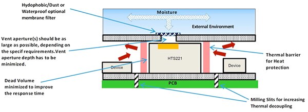
To optimize sensor accuracy and reliability, developers need to carefully consider the placement of the sensor on the board as well as the nature of the housing used to protect sensitive sensors such as the HTS221 from contamination from the environment, or heat from other electronic components (Figure 1).

Figure 1: To ensure accurate measurement of temperature and humidity, developers need to employ physical design methods recommended by STMicroelectronics to protect the sensor from external factors including dust and thermal sources. (Image source: STMicroelectronics)
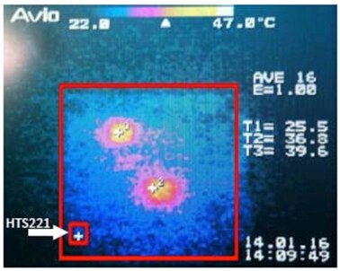
After developers complete the pc board design, STMicroelectronics even recommends use of infrared imaging techniques to confirm that the device is placed as far as possible from other heat-generating devices (Figure 2).

Figure 2: STMicroelectronics recommends use of thermal imagining methods to ensure that a temperature sensor such as the HTS221 (lower left) is placed as far away as possible from heat sources that share the printed circuit board. (Image source: STMicroelectronics)
Software developers need to be equally cautious in controlling an integrated sensor and acquiring data from it. To manage its integrated signal chain, the HTS221 provides registers for device identification, configuration, control, status, calibration, and data output. In some cases, the device uses multiple registers.
For example, the device uses three separate registers for control features such as enabling its internal heater, controlling data rate selection, and managing its output signals. At the same time, accurate data sampling requires more than simply accessing a data output register. As demonstrated below, developers need to adjust raw data using calibration coefficients maintained in the device’s integrated flash memory.
Achieving reliable temperature and humidity data requires careful attention at each stage of hardware and software design. For an IoT application that requires multiple sensors, developers need to address these issues for each separate sensor, while avoiding electrical or physical interaction among the sensors in the final board design. STMicroelectronics offers a shortcut through this maze of design challenges.
Multisensor IoT kit
The STMicroelectronics Discovery Kit for IoT offers a complete development platform for designing wireless sensor systems for IoT applications. Based on the ARM® Cortex®-M4 core processor, the onboard STM32L475VGT6 low-power MCU integrates 1 Mbyte of flash memory and 128 Kbytes of SRAM. It has an extensive set of integrated analog peripherals including three high-speed, 12-bit, analog-to-digital converters (ADCs), two digital-to-analog converter (DAC) channels, op amps, comparators, and a voltage reference. The MCU also contains a full complement of digital peripherals including a real-time clock (RTC), pulse-width modulation (PWM) timers, and multiple general purpose timers. Along with dozens of IOs, the device provides several standard interfaces including USB, USART, SPI, and CAN.
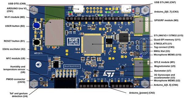
Leveraging the MCU’s extensive peripheral support, the development board packs a broad set of connectivity options and sensors into a 90 mm x 62 mm footprint (Figure 3). The board’s support of multiple options frees developers to focus on the requirements of the IoT application rather than individual sensor implementations or wireless technology support. The board offers wireless options ranging from near-field to extended range wireless connectivity. Along with its on-board dynamic NFC, the board offers Bluetooth and Wi-Fi connectivity using the SPBTLE-RF module and the Inventek ISM43362-M3G-L44 module, respectively. For low-power sub-GHz designs, ST provides two versions of the kit. The B-L475E-IOT01A1 uses the SPSGRF-915 to support 915 MHz communications, while the B-L475E-IOT01A2 uses the SPSGRF-868 to support 868 MHz communications.

Figure 3: The STMicroelectronics IoT kit brings out the STM32L475VGT6 MCU’s extensive peripheral support to offer an extensive set of connectivity options and multiple sensors for environmental and motion sensing. (Image source: STMicroelectronics)
Besides its multiple wireless options, the board’s extensive complement of on-board sensors reduces the chance that developers will need to spend time building sensor hardware interfaces and drivers before starting their project. Along with two MP34DT01 MEMS microphones, the board offers multiple sensors for environmental and motion sensing. For environmental sensing, the board provides the HTS221 humidity and temperature sensor along with the LPS22HB barometer. For motion sensing, the kit includes the LIS3MDL magnetometer, LSM6DSL accelerometer/gyroscope, and VL53L0X time-of-flight sensor.
Integration details
Along with the sensor hardware on the board, the kit includes comprehensive documentation, full schematics, and an extensive software package. As a result, hardware developers can accelerate custom sensor design projects by referencing the detailed design used for integration of sensors such as the HTS221 (Figure 4).

Figure 4: The ST IoT kit provides a complete reference design including detailed schematics such as the hardware interface for the HTS221 humidity and temperature sensor. (Image source: STMicroelectronics)
Similarly, software developers can examine source code provided in the package to understand critical methods such as correction of acquired data using the sensor’s integrated table of compensation coefficients (Listing 1). The detailed documentation walks developers through solutions to common problems such as interpolation of compensation coefficients for raw data lying between values supported directly in the compensation table.
float HTS221_H_ReadHumidity(uint16_t DeviceAddr)
{
int16_t H0_T0_out, H1_T0_out, H_T_out;
int16_t H0_rh, H1_rh;
uint8_t buffer[2];
float tmp_f;
SENSOR_IO_ReadMultiple(DeviceAddr, (HTS221_H0_RH_X2 | 0x80), buffer, 2);
H0_rh = buffer[0] >> 1;
H1_rh = buffer[1] >> 1;
SENSOR_IO_ReadMultiple(DeviceAddr, (HTS221_H0_T0_OUT_L | 0x80), buffer, 2);
H0_T0_out = (((uint16_t)buffer[1]) << 8) | (uint16_t)buffer[0];
SENSOR_IO_ReadMultiple(DeviceAddr, (HTS221_H1_T0_OUT_L | 0x80), buffer, 2);
H1_T0_out = (((uint16_t)buffer[1]) << 8) | (uint16_t)buffer[0];
SENSOR_IO_ReadMultiple(DeviceAddr, (HTS221_HR_OUT_L_REG | 0x80), buffer, 2);
H_T_out = (((uint16_t)buffer[1]) << 8) | (uint16_t)buffer[0];
tmp_f = (float)(H_T_out - H0_T0_out) * (float)(H1_rh - H0_rh) / (float)(H1_T0_out - H0_T0_out) + H0_rh;
tmp_f *= 10.0f;
tmp_f = ( tmp_f > 1000.0f ) ? 1000.0f
: ( tmp_f < 0.0f ) ? 0.0f
: tmp_f;
return (tmp_f / 10.0f);
}
Listing 1: By examining source code provided in the ST IoT kit software package, developers can gain experience with sensor software design patterns such as device level data acquisition and data compensation as demonstrated in this function provided in the HTS221 software driver module. (Code source: STMicroelectronics)
The software package offers complete application software samples that let developers quickly begin working with the board. ST preloads the demonstration firmware in the STM32L475VG MCU’s flash memory. Consequently, developers can simply attach the board to a USB port on their Windows or MacOS computer and begin evaluating the onboard sensors. When they are ready to focus on their application requirements, developers can build upon the existing software environment, or take advantage of its layered architecture to introduce more specialized hardware drivers or middleware (Figure 5).

Figure 5: Designed to support multiple development boards including the ST IoT kit, the ST software environment uses a layered architecture to simplify development and customization of secure IoT applications. (Image source: STMicroelectronics)
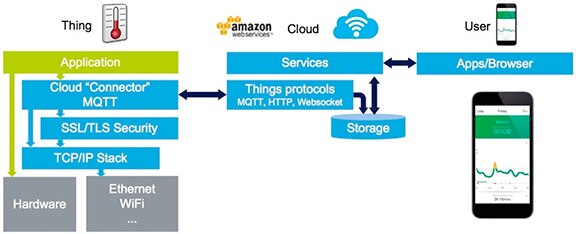
At the lowest layers of the software architecture, the development environment provides the required board support package (BSP) and hardware abstraction layer (HAL) modules needed to isolate software from hardware dependencies. Among the middleware components, ST provides transport layer security (TLS) support with mbedTLS, lightweight TCP/IP support with LwIP, and real-time operating system (RTOS) services with FreeRTOS. For IoT developers, the Amazon Web Services (AWS) middleware component offers a path to rapid development of end-to-end IoT applications (Figure 6).

Figure 6: The AWS module provided with the ST IoT kit software package supports rapid implementation of end-to-end IoT applications built on AWS services including AWS Mobile for connected mobile apps. (Image source: STMicroelectronics)
End-to-end IoT application
Included in a free expansion to ST’s STM32Cube development environment, the Amazon Web Services middleware component provides a set of services designed to connect the ST IoT kit to the AWS IoT platform. Intended to provide a common platform for IoT applications, the AWS IoT service uses the MQTT (MQ Telemetry Transport) messaging protocol to connect IoT end devices to backend AWS cloud services. In the AWS IoT protocol, sensor systems use MQTT messaging to subscribe and publish data in a simple JSON format (Listing 2). Once the data reaches the cloud, developers can take advantage of the full breadth of AWS services including AWS Mobile for app development.
{
"state": {
"reported": {
"temperature": 27.64,
"humidity": 38.42,
"pressure": 995.94,
"proximity": 8191,
"acc_x": -15, "acc_y": 2, "acc_z": 1020,
"gyr_x": -980, "gyr_y": -4060, "gyr_z": 1750,
"mag_x": -140, "mag_y": 90, "mag_z": 319
}
}
}
Listing 2: The ST IoT kit software package provides an implementation of the AWS IoT MQTT protocol, which transmits sensor data using a simple JSON format as demonstrated in this sample sensor data payload. (Image source: STMicroelectronics)
Within the ST IoT development environment, the AWS module included in the software package provides the MQTT client services that form an integral part of the AWS IoT architecture. The AWS module itself builds on the TLS security stack provided by mbedTLS and TCP/IP services provided by the Wi-Fi library for the ST IoT kit. (Systems using Ethernet connection draw on the LwIP module for TCP/IP services.)
To help developers examine details of a complete IoT workflow, ST’s AWS package includes sample applications that demonstrate use of the ST IoT kit to transmit data to the AWS cloud. In one sample application, the software sends sensor data to the AWS IoT service when the developer pushes a button on the ST IoT kit board. The provided source code allows developers to examine the key design patterns used to create the MQTT payload that underlies AWS IoT transactions (Listing 3), and to publish the sensor data payload when the user presses a button on the board (Listing 4).
int PrepareMqttPayload(char * PayloadBuffer, int PayloadSize)
{
char * Buff = PayloadBuffer;
int BuffSize = PayloadSize;
int snprintfreturn = 0;
TEMPERATURE_Value = BSP_TSENSOR_ReadTemp();
HUMIDITY_Value = BSP_HSENSOR_ReadHumidity();
PRESSURE_Value = BSP_PSENSOR_ReadPressure();
PROXIMITY_Value = VL53L0X_PROXIMITY_GetDistance();
BSP_ACCELERO_AccGetXYZ(ACC_Value);
BSP_GYRO_GetXYZ(GYR_Value);
BSP_MAGNETO_GetXYZ(MAG_Value);
snprintfreturn = snprintf( Buff, BuffSize, "{\n \"state\": {\n \"reported\": {\n"
" \"temperature\": %.2f,\n \"humidity\": %.2f,\n \"pressure\": %.2f,\n \"proximity\": %d,\n"
" \"acc_x\": %d, \"acc_y\": %d, \"acc_z\": %d,\n"
" \"gyr_x\": %.0f, \"gyr_y\": %.0f, \"gyr_z\": %.0f,\n"
" \"mag_x\": %d, \"mag_y\": %d, \"mag_z\": %d\n"
" }\n }\n}",
TEMPERATURE_Value, HUMIDITY_Value, PRESSURE_Value, PROXIMITY_Value,
ACC_Value[0], ACC_Value[1], ACC_Value[2],
GYR_Value[0], GYR_Value[1], GYR_Value[2],
MAG_Value[0], MAG_Value[1], MAG_Value[2] );
/* Check total size to be less than buffer size
* if the return is >=0 and <n, then
* the entire string was successfully formatted; if the return is
* >=n, the string was truncated (but there is still a null char
* at the end of what was written); if the return is <0, there was
* an error.
*/
if (snprintfreturn >= 0 && snprintfreturn < PayloadSize)
{
return 0;
}
else if(snprintfreturn >= PayloadSize)
{
printf("Data Pack truncated\n");
return 0;
}
else
{
printf("Data Pack Error\n");
return -1;
}
}
Listing 3: Using the ST IoT kit software package, developers can take advantage of low-level functions such as PrepareMqttPayload(), which collects data from the board’s sensors and prepares a JSON-formatted payload for delivery using other MQTT support functions. (Code source: STMicroelectronics)
if (bp_pushed == BP_SINGLE_PUSH)
{
if(strstr(ledstate, "Off")!= NULL)
{
strcpy(ledstate, "On");
}
else
{
strcpy(ledstate, "Off");
}
msg_info("Sending desired LED state to AWS!\n");
/* create desired message */
memset(cPayload, 0, sizeof(cPayload));
strcat(cPayload, aws_json_desired);
strcat(cPayload, "{\"LED_value\":\"");
strcat(cPayload, ledstate);
strcat(cPayload, "\"}");
strcat(cPayload, aws_json_post);
paramsQOS1.payloadLen = strlen(cPayload) + 1;
do
{
rc = aws_iot_mqtt_publish(&client, cPTopicName, strlen(cPTopicName), ¶msQOS1);
if (rc == AWS_SUCCESS)
{
msg_info("\nPublished to topic %s:", cPTopicName);
msg_info("%s\n", cPayload);
}
if (publishCount > 0)
{
publishCount--;
}
} while(MQTT_REQUEST_TIMEOUT_ERROR == rc && (publishCount > 0 || infinitePublishFlag));
}
Listing 4: Source code provided in the ST IoT kit software package demonstrates a basic main loop for an IoT sensor application that transmits a payload of MQTT data when the user pushes a button on the IoT kit board. (Code source: STMicroelectronics)
Along with this basic IoT application example, the ST software package lets developers explore a number of additional features required in any practical application. For example, another sample application supplements the basic workflow described earlier with a firewall to protect the IoT device from unauthorized external access.
Although simple in concept, this firewall application demonstrates the use of protection mechanisms built into the STM32L475xx MCU itself. While software protection mechanisms often leave gaps in security, the MCU’s built-in firewall protection mechanism enforces controlled access to configurable segments of SRAM or flash memory. Authorized code can only access these protected segments through a single entry point, which helps eliminate security flaws. The firewall application uses this mechanism to protect the AWS private key used for authenticated access to the AWS cloud.
Developers can easily explore the different sample AWS applications simply by flashing the board with the application images provided in the software package and interacting with the application through a UART console. As needed, developers can easily extend the ST IoT kit to meet their unique IoT application requirements. If the application requires additional specialized hardware, developers can use the board’s Arduino Uno V3 and PMOD connectors to extend it with add-on boards. To meet additional software requirements, developers can work in familiar integrated development environments (IDEs) to modify or extend the provided source code. The package comes with support for multiple software development environments including Keil MDK, IAR Systems Embedded Workbench, ARM mbed Enabled, and any GCC enabled IDE including the free Eclipse-based SW4STM32 System Workbench for STM32 MCUs.
Conclusion
IoT applications typically rely on wireless connectivity to combine data from multiple sensor modalities to present a broader view of the environment, equipment, or individuals. For IoT developers, the task of designing a suitable multisensor wireless system can present multiple challenges that typically slow development.
Supporting multiple sensors and connectivity options, the STMicroelectronics IoT development kit offers a pre-built solution for complex IoT designs. Using the kit hardware and software, developers can rapidly implement sophisticated IoT designs and integrate them in end-to-end IoT applications built on the AWS cloud.

免责声明:各个作者和/或论坛参与者在本网站发表的观点、看法和意见不代表 DigiKey 的观点、看法和意见,也不代表 DigiKey 官方政策。


 中国
中国