Using Spread-Spectrum Techniques to Manage Switching Power Supply EMI
投稿人:电子产品
2014-06-03
Switching DC/DC power supplies and regulators, regardless of whether IC, module, or chassis, are generally preferred over linear supplies, and with good reason. In general, they are much more efficient, resulting in reduced power use and cost, longer run time, and less heat to dissipate. (Note: There are cases where the linear supply may be more efficient, especially when the input/output voltage differential is small.¹)
However, there is a problem with switching supplies which affects many designs. Due to their inherent internal switching action, they generate more noise than linear supplies. The noise frequency is a function of the underlying switching frequency, which typically is between 100 kHz and several MHz, depending on design and application, and includes several harmonics.
In designs which are capturing low-level sensor signals, this noise may be unacceptable and additional filtering must be used to keep that noise out of the sensitive front end. In other designs, such as consumer products and autos, the noise is not a problem for the system's performance itself, but the radiated noise as EMI means the unit will fail the relevant regulatory standards such as CISPR 252² [CISPR is an acronym from the French name for the IEC committee known in English as the International Special Committee on Radio Interference]. Yet, going back to a linear supply may not be acceptable for reasons of footprint, BOM cost, dissipation, or power use.
Fortunately, vendors of switching-supply control ICs have devised a way to minimize the noise problem. First, they are slowing and managing the slew rates and transitions of the converter clock and timing signals, to reduce some of the emissions. However, they have also gone further: some designs have adapted a technique used in communications spectrum management, encoding, and security to mitigate the noise problem. This spread-spectrum approach is the basis for frequency- and time-hopping systems used in devices where the user is not assigned a fixed frequency or time slot. Other designs use a triangle wave to modulate, and thus sweep the clock frequency across a modest range above and below the nominal value.
The problem and the principle
It is important to be clear about the basic parameters of EMI. The three basic factors are spectrum, energy, and amplitude:
- Spectrum is obvious: it is those frequencies or band of frequencies at which the EMI is a concern.
- Energy is the total EMI in the spectrum of interest; note that energy is the time-integral of power.
- Amplitude is the value of the energy measured at specific points in the spectrum.
Conducted EMI energy can be reduced by use of ferrite beads, while shielding can attenuate the radiated energy. These techniques can be effective in many cases, but each has costs in board space, assembly effort, and bill of materials. Even when attenuated, however, EMI may still be too high for various situations.
That is where spread-spectrum comes in. The basic idea is to take the fixed frequency of the switching converter clock, and transform it into a non-fixed frequency. This does not mean the circuit simply changes it to another fixed frequency where EMI is less of a concern. By modulating the switching frequency, the peak energy is lowered and distributed to other frequencies and their harmonics.
There are two ways to implement the frequency spreading. In the simplest approach, a triangle waveform controls the clock, sweeping it around the nominal value (Figure 1).

Figure 1: A triangle waveform (shown) or a trapezoidal one can be used to modulate the switcher’s clock and thus sweep its operating frequency through a band rather than operate at a fixed frequency.
In a more-complex but more-effective approach, the clock frequency is randomly jittered, although its nominal or average frequency remains the same as before the spreading was applied. This jittering of the clock frequency is not truly random; instead, it is done by using a pseudorandom code sequence which controls (modulates) the clock frequency (Figure 2). However, for this purpose, such clocking variation is "random enough." The resultant total spectrum spread is usually between one and ten percent of the nominal frequency (±0.5 to ±5 percent) but it can be more.

Figure 2: An advanced, but more complicated approach uses a pseudorandom digital sequence to jitter the clock, resulting in a wideband operating range evenly spread throughout the span (Courtesy of National Instruments).
For applications where the noise is affecting sensitive parts of the circuit, spread-spectrum can move the EMI frequency outside the band of concern. This can solve many in-circuit problems, but it is not a cure-all, as the EMI energy may still overload a sensitive front end and push it into a non-linear mode or even saturation.
However, spread-spectrum's real value is in enabling a product to pass regulatory compliance thresholds. The reason is that these thresholds specify maximum EMI energy at specific points in the spectrum, as well as anywhere within a defined band of the spectrum. This energy is determined by measuring the amplitude at these points. Spread-spectrum broadens the EMI energy across the frequency spectrum, so that the values in any given band are lowered, hopefully below the regulatory limit. Note that the total EMI energy is unchanged, since there is no attenuation.
IC vendors embed the function
IC vendors have built the functions of spread-spectrum clock modulation into some of their switcher IC and modules, as well as into clock controllers that act as the system clock for one or more power-regulator ICs.
Linear Technology Corp. offers the LTC6902, a precision, low-power, easy-to-use oscillator specifically designed to drive the clock input of one or more switching regulators, in single or multiphase topologies (Figure 3).

Figure 3: The LTC6902 clock oscillator from Linear Technology Corp is specifically designed for single and multiphase supplies; note the 9-bit pseudorandom sequence generator that drives a DAC, which in turn controls the clock frequency.
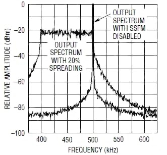
The oscillator nominal frequency can range over a wide span of 5 kHz to 20 MHz, and is set by a single external resistor. The IC also provides an optional pseudorandom-based spread-spectrum modulation mode, with span also set by an external resistor. In this mode, the peak amplitude of the EMI energy can be reduced by up to 20 dB (Figure 4).

Figure 4: In a typical setup, the spread-spectrum mode reduces the EMI’s sharp peak at the switching frequency by 20 dB, as it spreads its energy over a wider band.
If you are working in the automotive environment, where switch mode regulators are commonly used, you know that they have to be designed to mitigate their inherently noisy nature. This is not always easy, especially since the power and amount of electronics in a car is growing. To help, Linear has created a video explaining how spread-spectrum frequency modulation is employed in its LT3795 LED driver, achieving high-power automotive LED driving conversion, robust short-circuit protection, and reduced EMI via the use of a triangle spread-spectrum frequency modulation. In this case the spread-spectrum frequency modulation of the LED driver is specifically designed to work with the LED driver and prevent possible LED flicker when the LEDs are run at full power and while they are PWM dimmed for brightness control.
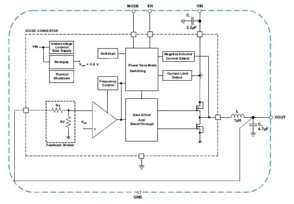
The TPS8267x family of ICs from Texas Instruments comprises a series of complete 600 mA, DC/DC step-down power-supply devices intended for low-power applications (Figure 5).

Figure 5: Texas Instruments’ TPS8267x family of low-power DC/DC ICs uses a basic triangle waveform to modulate the clock over a 20 percent range centered on the nominal clock frequency.
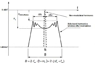
The frequency dithering scheme is modulated with a triangle profile and a modulation frequency. Included in the ICs are the switching regulator, inductor, and input/output capacitors; no additional components are required to use it. The spread-spectrum architecture varies the switching frequency by approximately ±10 percent of the nominal switching frequency, thereby significantly reducing the peak radiated and conducting noise on both the input and output supplies (Figure 6).

Figure 6: Using the spread-spectrum mode of the TPS8267X family, the non-modulated peak of radiated noise is now spread out over a band of well-defined harmonics.
Alternate views
Spread-spectrum clocking of switching DC/DC regulators can lower both conducted noise and radiated EMI at given bands in the overall spectrum, thus improving circuit performance and allowing the final product to meet regulatory mandates. Design engineers are of two views on using spread-spectrum techniques: some feel it is an effective solution to a difficult problem, especially in the face of "arbitrary" EMI emission standards; others feel it is a "cheat" which does not solve the underlying problem but merely disguises it and potentially makes it a problem for other parts of the circuit and spectrum.
Where you stand on the matter depends on your project's priorities, budget, and time crunch. Spread-spectrum clocking of switching converters is in widespread and successful use, but it cannot solve all EMI problems and must be used with caution and careful consideration of the technical situation.
In summary, switching power supplies are generally much more efficient than older, linear supplies, but they have an unavoidable drawback: they generate switching noise. This noise has two consequences: it can affect circuit performance and also cause the product to not meet the various regulatory standards for maximum generated EMI. To overcome this, some switchers use spread-spectrum techniques. This article examined the switching-noise problem with respect to sensitive analog front ends and radiated EMI, the use of spread-spectrum in the context of power-supply noise, what using it can (and cannot) accomplish, and presented two representative components which implement spread-spectrum topology but in very different ways.
References:
免责声明:各个作者和/或论坛参与者在本网站发表的观点、看法和意见不代表 DigiKey 的观点、看法和意见,也不代表 DigiKey 官方政策。


 中国
中国