Selecting MCU Peripherals for Efficient IoT Sensor Fusion Designs
投稿人:电子产品
2016-02-04
Sensors are becoming a ubiquitous element in the transformation of the electronics infrastructure into the Internet of Things (IoT). Sensors will provide the data used to manage and control electronic systems in the car, home, workplace, factory floor, and just about everywhere in between. Sensors are expanding not only in their reach, but also in their capabilities. Exciting new capabilities can be created when multiple sensors are co-located and can exchange and enhance individual measurements. In these types of designs the sensor can implement advanced functions, often described as sensor “fusion,” that provide new and innovative capabilities.
Sensor-fusion algorithms have been implemented in chemical-process control systems for decades, so the concept is not really new. Most chemical-process control systems need a variety of sensor readings to determine the right settings for a value, flow rate, or setting. You wouldn’t consider managing a chemical process without sensing pressure, temperate, and volume, right? (Remember PV = nRT?)
It’s easy to require that your new sensor-fusion design includes a variety of sensors so your fancy new algorithm has all the data it’s going to need; but at some point your MCU will need to connect to all these sensors while providing the data at the rates your algorithm will require. Oh, and by the way you need to retain lots of MCU compute capability, so the processor can’t be bothered with managing all the sensor data in real time.
Fortunately, MCU manufacturers have been extending the capabilities of their MCU peripherals, so that designs can use the full capabilities of multiple interfaces without burdening the processor with a significant amount of overhead. This article will look at an example implementation of a sensor-fusion design, to illustrate how selecting the right peripheral for each sensor can be critical to your design’s success.
An example design
One of the more common sensor-fusion designs we are going to see in the next couple of years will be used to track and record the environment around an object of interest. The object of interest could be a package in transit, a parked car, a bicycle on the move, or your dog in the yard. Clearly the sensor logs and any sensor fusion algorithms will be looking for specific environmental measurements, but there are some popular ones we could include in our example design. Let’s assume we will want to provide temperature, humidity, vibration, pressure, and acceleration. Let’s also add a requirement for capturing sound to cover the cases where voice commands are used or when capturing ambient noise is required, perhaps to verify industrial standards for noise level are being complied with. These types of readings are varied enough to provide us with some design challenges so we can explore specific MCU features that are critically important for efficient sensor-fusion designs.
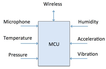
A simplified block diagram for our example design is illustrated in Figure 1. A key design goal is to find the optimal MCU interface to use for each sensor, a connection that can provide sensor data at the rate the sensor-fusion algorithm requires. In our example design low power will also be a critical requirement since battery operation is assumed. Getting the most data and the most processing capability on limited power will thus be our main design goals.

Figure 1: Environmental monitor sensor simplified block diagram.
The audio, temperature, pressure, acceleration, vibration, and humidity sensors all connect directly to the MCU. A wireless connection, perhaps a low-power short-range standard such as Bluetooth Low Energy, allows the sensor to supply data via an aggregation unit to the cloud. Algorithm enhancements or maintenance updates can be made by downloading MCU code updates from the cloud. These updates can be used to extend sensor lifetime or to re-task the sensor for different conditions or changing requirements.
Each sensor has different constraints on speed, latency, power, and measurement frequency. The primary design task is to optimize these interfaces to provide the fusion algorithm with the data needed, at the optimal time and with as little power consumption as possible. The first place to start in determining optimal connections is to separate out low-speed connectivity and high-performance connectivity requirements.
Low-speed connectivity
Many sensors do not need high-speed connectivity and thus may use an older, low-speed serial interface such as a UART. In our example design we will assume that the pressure sensor uses a UART-style interface and communicates only a few times every second. This rate is usually more than sufficient to track both long-term and sudden pressure changes. The use of a UART interface can present the design with a, perhaps non-intuitive, design problem. Because the frequency is low, you might expect the power requirement to be low as well. Unfortunately, you can run into the situation where, because the transmission frequency is low, the UART will need to stay on for a long time. Power will be expended as long at the UART is active.
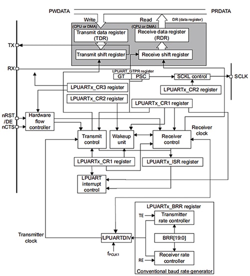
What we need for our example design is a power-efficient UART peripheral, one that uses little power when active and can be easily turned off when it is not needed. Several MCUs now include specialized low-power UARTs with these characteristics and the low-power UART illustrated in Figure 2 below from STMicroelectronics shows just how power efficient a UART can be.

Figure 2: STM32L low-power UART block diagram. (Courtesy of STMicroelectronics)
The typical UART functions – transmit data register, receive data register, control registers, baud-rate selection, and overall control units – are all evident in the block diagram, but what is not easily spotted is that the UART can operate even when the MCU is in the low-power Stop mode. The UART can wait for an incoming data frame and wake the MCU from Stop mode with an interrupt. The CPU can then move the data to memory or begin processing immediately if the UART data is an important element in the sensor-fusion algorithm. Because the low-power UART peripheral can receive the data while the CPU is in the Stop mode, the amount of power required during the transfer is much reduced, which increases our power efficiency substantially. Look for similar low-power features when you have low-speed serial interfaces you need to connect to your MCU.
High-performance connectivity
In some sensor applications it’s important to access sensor data frequently or at a high data rate. In our example design the audio sensor requires the highest bandwidth. Other types of sensors, e.g., light, temperature, pressure, and position, change infrequently and can thus be monitored at a much lower rate. There are multiple choices for high-speed interfaces offered on most MCUs with SPI, QSPI, and I²C as popular choices. As one example, the Atmel SAM4S4A MCU supports SPI and I²C with multiple channels. An additional capability of this device is that SRAM can be retained even in very-low-power modes so that sensor data packets, when stored in SRAM, will not be lost. Look for this capability when low power is an overriding concern.
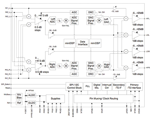
Many MCUs support the popular I²S audio interface, and often this is the obvious choice for audio-processing applications. Modern Audio Codecs typically support multiple interfaces however, so you can select the one right for your application. The Texas Instruments TLV320AIC3254 stereo audio codec, (Figure3), supports I²S, I²C, and SPI so you have a variety of interface options.

Figure 3: Texas Instruments’ audio codec has multiple serial interface support. (Courtesy of Texas Instruments)
The I²S interface is an excellent choice when your application is streaming audio data. Let’s assume that in our example the sensor needs to measure audio levels and frequencies infrequently (maybe at most once a second) as a way to test that the environment is complying with regulations for sound exposure for a workforce on a factory floor. It will be important to capture a fraction of a second’s worth of sound without dropping any data and without interfering with other measurements. The I²S interface is a good choice in this case and allows independent operation from other I²C or SPI ports.
The use of I²S will also allow us to minimize power consumption since it is only on during the audio-capture period. Often I²S can be used in conjunction with a DMA so that the CPU can be put in a low-power mode until the data is all captured and ready to process. Alternatively, the CPU could process data while it is being captured. This might end up reducing power if the total “on time” of the audio function is reduced. Consider comparing these two approaches in your design and select the one with the best efficiency for your requirements.
Don’t forget analog
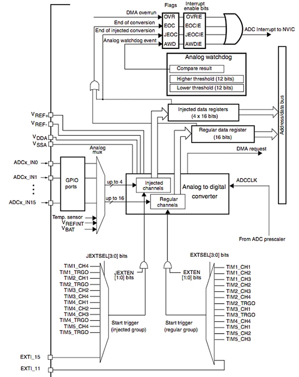
Even though many sensors use serial interfaces, do not forget that a simple analog-to-digital converter (ADC) can be used for many sensor applications. Some ADCs can operate independently from the CPU and this makes it easy to put the CPU into a low-power mode while the conversion is taking place. The STM32F4 MCU, for example, has an ADC that can use the Direct Memory Access (DMA) controller to move captured data directly to memory. The ADC can also be started via the timer counter blocks so that periodic measurements can be easily made without CPU intervention. These start trigger signals as seen at the bottom of the block diagram of the STM32F4 ADC in Figure 4.

Figure 4: STMicroelectronics STM32F4 MCU ADC block diagram. (Courtesy of STMicroelectronics)
To further improve efficiency an analog watchdog feature allows very precise monitoring of the converted voltage of one, some, or all selected channels. An interrupt is generated when the converted voltage is outside the programmed thresholds. This is particularly useful in our example environmental monitoring design since the CPU need not be active unless a measurement strays outside the “safe” zone. This reduces power consumption and allows the CPU to focus on key processing requirements.
Conclusion
For sensor-fusion designs, efficient interfaces that reduce CPU overhead are critical. Freeing up the CPU so it can process a variety of sensor data with algorithms that combine or fuse data to identify important events creates an intelligent sensor-fusion device. These smart devices will be critical elements in the expanding Internet of Things environment.
For more information on the parts discussed in this article, use the links provided to access product pages on the DigiKey website.
免责声明:各个作者和/或论坛参与者在本网站发表的观点、看法和意见不代表 DigiKey 的观点、看法和意见,也不代表 DigiKey 官方政策。


