使用多协议 I/O 集线器和转换器优化工业 4.0 通信架构
投稿人:DigiKey 北美编辑
2024-10-01
通信协议对于支持工业 4.0 和工业物联网 (IIoT) 网络中的实时数据传输和控制非常重要。传感器、执行器、电机驱动器和控制器都有各自特定的通信需求。“全能型”通信协议并不存在。
虽然没有一种协议能满足每种应用的需求,但不同设备之间通常需要连接。传感器必须与控制器相连,控制器必须与使用不同协议(如 IO-Link、Modbus 和多种形式的以太网)的各种系统元件相连。
很多情况下,整个机器需要连接到云。这就导致通信架构复杂,协议繁多。为了应对这一挑战,机器设计人员可以采用多协议输入/输出 (I/O) 主设备、集线器和转换器。
本文首先回顾了常见的工业 4.0 通信协议及其在网络层次结构中的位置。然后介绍了一系列来自 Banner Engineering 的 I/O 主设备、集线器和转换器,并探讨了这些器件的工作方式,以及它们如何支持复杂的工业 4.0 和 IIoT 通信架构。
什么是 OSI 七层模型?
网络通信协议通常以开放系统互连 (OSI) 七层模型为背景进行描述。该模型首先有三个介质层,处理硬件方面的问题,如物理连接、数据链路连接和网络连接。
接下来三层重点用于数据寻址,包括传输、会话和呈现过程。
模型的第七层是应用层,提供用户与网络之间的接口。Modbus 和 PROFINET 等协议都位于这一层。OSI 模型与 EtherNet/IP 等其他协议的关系更为松散。
就 EtherNet/IP 而言,应用层包括网络访问 (HTTP)、电子邮件 (SMTP)、文件传输 (FTP) 等过程。三个主机层执行传输控制协议/互联网协议 (TCP/IP) 过程,用于建立会话、纠错等。介质层包括物理 10 Base-T 连接,以及以太网数据链路和网络连接的实现(图 1)。
 图 1:EtherNet/IP 与 OSI 七层模型的关系。(图片来源:Banner Engineering)
IO-Link 适合用在哪里?
IO-Link 是一种单滴数字通信接口 (SDCI),适用于小型传感器、执行器和类似设备,能够将双向通信扩展到工厂车间的各个设备。该协议符合 IEC 61131-9 标准,设计可与基于 Modbus、PROFIBUS、EtherNet/IP 等的工业网络架构兼容。
IO-Link 使用主设备将 IO-Link 设备连接到更高层次的协议(如 Modbus),后者提供与可编程逻辑控制器 (PLC)、人机界面 (HMI)、云数据服务 (CDS) 等数据消耗设备的连接。在最底层,IO-Link 使用集线器汇集多个设备,并将数据向上馈送至主设备。此外,还可以使用 IO-Link 转换器的模拟电压将模拟传感器添加到 IO-Link 网络中(图 2)。
 图 2:IO-Link 转换器、集线器和主设备可从现场设备收集数据,并将其推送至 PLC、HMI 和 CDS 等数据消费者。(图片来源:Banner Engineering)
为什么将 IO-Link 与其他协议相结合?
大规模定制和灵活的生产流程是工业 4.0 的显著特征。将 IO-Link 与其他协议相结合,可提高工业 4.0 工厂的灵活性和多功能性。IO-Link 的优点包括:
- Modbus 对模拟设备(如某些传感器)的支持有限,而 IO-Link 则同时兼容数字和模拟设备。
- 使用同时支持 IO-Link 和更高层协议(如 Modbus TCP 或 EtherNet/IP)的网关,可提高工厂自动化和扩展能力,并可在现场级传感器网络和工业网络通信主干网之间发挥桥梁作用。
- IO-Link 为所有传感器提供统一标准化配置流程以提高运行效率,使用相同型号的传感器时,也能利用 IO-Link 自动更换有缺陷的传感器。
- 凭借 IO-Link 的数据收集和通信功能,更能掌握各个传感器以及分散传感器网络的运行情况,并可加快将数据传输到 PLC 和云的速度。
如何将 Modbus 和 IO-Link 相结合?
首先要考虑的一种工具是混合 I/O Modbus 集线器,如 8 端口双模转 Modbus 的 R95C-8B21-MQ。这款离散双模转 Modbus 集线器将两个离散通道分别连接至 8 个不同的端口,使得能够通过 Modbus 寄存器对这些端口进行监控和配置。
混合 I/O Modbus 集线器配有 4 个可配置的模拟输入(电压或电流)和 4 个模拟输出,以及 8 个可配置的 PNP(拉电流)或 NPN(灌电流)离散输入和输出,从而提高应用灵活性。
DXMR90-X1 工业控制器可用作 IIoT 解决方案的平台。这款控制器可以整合多个来源的数据,以便进行本地数据处理和访问。DXMR90 包含单独的 Modbus 客户端,支持与多达 5 个独立串行网络同时通信。
DXMR90-X1 包括一个母头 M12 D-Code 以太网连接器和四个用于 Modbus 主设备连接的 M12 母接头。其他 DXMR90 型号配有两个母头 M12 D-Code 以太网连接器和四个用于 Modbus 客户端连接的 M12 母接头;或者配有一个母头 M12 D-Code 以太网连接器和四个用于 IO-Link 主设备连接的 M12 母头连接器。
所有 DXMR90 控制器还包括一个用于输入电源和 Modbus RS-485 的 M12 公头(端口 0)和一个用于菊花链端口 0 信号的 M12 母头。DXMR90-X1 的其他特性包括(图 3):
- 将 Modbus RTU 转换为 Modbus TCP/IP、EtherNet/IP 或 Profinet
- 内部逻辑可由操作规则驱动以便于编程,或以 MicroPython 和 ScriptBasic 驱动,用于开发更复杂的解决方案
- 支持互联网协议,包括 RESTful 和 MQTT
- 非常适合 IIoT 数据分析、状态监测、预测性维护、整体设备效率 (OEE) 分析、诊断和故障排除
 图 3:DXMR90-X1 控制器可与 R95C 混合 I/O Modbus 集线器配合使用。(图片来源:Banner Engineering)
什么是多协议支持?
DXMR110-8K 8 端口 IO-Link 主设备是一款结构紧凑的多协议智能控制器,可整合、处理和分发来自多个来源的 IO-link 和离散数据。接头包括:
- 两个母头 M12 D-Code 以太网连接器,用于菊花链和与上一层控制系统的通信
- 8 个 M12 母接头,用于连接 IO-Link 设备
- 一个 M12 公头,用于输入电源,一个 M12 母头,用于菊花链供电
DXMR110 支持云连接,并具有高级编程功能。ScriptBasic 和操作规则编程可用于创建和实施自定义脚本与逻辑,以优化自动化过程。
DXMR110 具有内部处理能力,可用于将数据处理向边缘转移,从而最大限度减少对控制柜中硬件的需求,并且不需要在 PLC 上使用 I/O 卡。集成式云连接支持从世界任何地方访问数据。最后,采用 IP67 外壳,无需使用控制柜,从而简化了在任何地点的安装(图 4)。
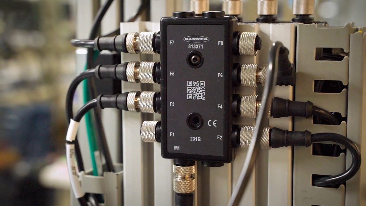
") 图 4:DXMR110-8K 8 端口 IO-Link 主设备是一种多协议智能控制器。(图片来源:Banner Engineering)
图 4:DXMR110-8K 8 端口 IO-Link 主设备是一种多协议智能控制器。(图片来源:Banner Engineering)
更多选择
上面介绍的设备并不是实施多协议工业通信解决方案的唯一选择。机器设计人员可以使用 Banner Engineering 的一系列远程 I/O 模块来优化系统设计、空间效率和性能。
Banner 提供的直插式转换器和主设备采用包塑设计,符合 IP65、IP67 和 IP68 的防护等级 (IP) 要求。R45C 系列直插式转换器和主设备提供了一个网关,采用 Modbus RTU 协议将 IO-Link 设备连接到 IIoT 网络或系统控制器。R45C-2K-MQ 型号可将两个 IO-Link 设备连接到一个 Modbus RTU 接口。
需要模拟信号时,设计人员可以使用 R45C-MII-IIQ Modbus 双模拟直插式 I/O 转换器。功能包括:
- 模拟输入。转换器接收到模拟输入时,会将输入值的数字表示发送到相应的 Modbus 寄存器。该寄存器可接受 0 至 11,000 mV 或 0 至 24,000 µA 的模拟输入。
- 模拟输出。转换器输出与数字输入相对应的模拟值。模拟输出范围为 0 至 11,000 mV 或 0 至 24,000 µA。
- 还可以检测和处理超出有效范围 (POVR) 的过程数据值,由转换器向系统发送信号。
当需要将单个模拟输入转换为 IO-Link 信号时,设计人员可以使用 S15C-I-KQ。这款圆柱形模拟电流转 IO-Link 转换器可连接 4 至 20 mA 电流源,并将相应值输出至 IO-Link 主设备。
Banner 提供各种 Modbus RTU I/O 模块,支持连接到 Modbus 或 IO-Link 网络的多个模拟和离散设备的连接。这些模块可以混合或配对使用,以支持灵活的系统设计以及互操作性(图 5)。
 图 5:用于 IO-Link 集成的 Banner 远程 I/O 解决方案的外形尺寸和配置示例。(图片来源:DigiKey)
能否集成无线协议?
Banner 的 Sure Cross DSX80 Performance 无线 I/O 网络解决方案可实现无线连接。其既可独立使用,也可通过 Modbus 或个人计算机或平板电脑连接到 PLC 主机。基础系统架构包括一个网关和一个或多个节点(图 6)。
 图 6:Banner 的 Sure Cross DSX80 Performance 无线 I/O 网络解决方案包括一个网关和一个或多个传感器节点。(图片来源:Banner Engineering)
实施 Sure Cross DX80 Performance 无线网络涉及三个要素:网络拓扑结构、主从设备关系和时分多址 (TDMA) 架构。
使用星形拓扑结构时,主设备与每个节点保持单独的连接。如果节点与主设备之间的连接失败,与其他节点的连接不会受到影响。
诸如 DX80G2M6-QC 之类的网关是主设备,负责发起与从设备的所有通信。使用 Modbus RTU RS-485 连接的网关充当 Modbus RTU 主控制器的从设备。单个无线网络可包括多达 47 个从节点。
从设备可以是无线节点,如 DX80N9Q45DT 双热敏电阻温度传感器节点、DX80N9Q45PS150G 压力传感器节点或振动和湿度传感器。
从设备无法发起与网关的通信,相互之间也无法通信。可添加诸如 DX80SR9M-H 等串行数据无线电,以扩大网络覆盖范围,从而适应物理尺寸较大的设施。
TDMA 是保障稳固连接与最低能耗的关键。网关中的 TDMA 控制器为每个节点分配特定的数据收发时间。网关的设备 ID 始终为 0。节点可使用设备 ID 1 到 47 按任意顺序编号。
为各个节点设置特定的通信时间,可消除节点之间发生冲突的可能性,从而提高效率。这样还能让节点在通信间歇期进入低功耗状态,只在指定时间唤醒。在两次传输之间关闭无线电可节省电力,延长电池供电节点的续航时间。
结语
要支持工业 4.0 和 IIoT 网络的高效运行,必须接入多种通信协议,如 IO-Link、Modbus、EtherNet/IP 等。Banner Engineering 为设计人员提供各种外形尺寸的 IO-Link 集线器、转换器和主设备,以支持优化的通信解决方案。
免责声明:各个作者和/或论坛参与者在本网站发表的观点、看法和意见不代表 DigiKey 的观点、看法和意见,也不代表 DigiKey 官方政策。