Material Advances Enable New Generation of Power Inductors
投稿人:DigiKey
2015-01-06
Designers building power inductors for today’s high-volume mobile markets face a difficult dilemma. On the one hand, the market demands higher performance systems with additional functionality running at higher current levels. On the other hand, it pressures product designers to squeeze that additional functionality into an ever-smaller package. Take the smartphone market as an example. Today’s phones are rapidly migrating from dual-core processors, running between 1 and 1.5 GHz, to quad-core processors running in excess of 2 GHz. Handset designers, accordingly, need choke coils for power supply circuits capable of supporting the higher operating currents used to deliver the phone’s new functionality. At the same time, phone designs are becoming increasingly smaller and thinner; so phone designers also need choke coils small enough to fit within their phone’s shrinking footprint.
The same trends can be seen in tablet design. Today’s customers demand larger, higher performance screens. They also expect lighter, thinner tablets. The original Apple iPad tablet, for instance, was 0.5 inches thick. At 0.29 inches, the latest iPad Mini is almost half as thick. Accordingly, tablet designers need choke coils capable of supporting ever higher levels of current, yet small enough to fit into the extremely low profile used by today’s leading products.
Unfortunately, those requirements run counter to traditional principles of choke coil design. Typically, choke coils are comprised of ferrite material. Since the saturation flux density of ferrite is not very high, the DC bias characteristics decline due to magnetic saturation when the choke coil is reduced in size. As a result, higher currents cannot pass through the choke. That is why designers are turning to inductors that use compacted metal powder made of high-saturation magnetic flux iron-based metal magnetic particles and an organic binder. In these products, the metal magnetic particles and the coil are formed at the same time. Then the binder is solidified and used to provide insulation between the metal particles.
Given the design trends in the mobile market, it appears that demand will grow rapidly for a new generation of choke coils that can deliver excellent performance characteristics in a smaller footprint. Nonetheless, how can manufacturers find a way to solve this problem and build the high performance yet compact inductors mobile designers need?
To solve this problem, engineers at Taiyo Yuden developed a new metal magnetic compacted powder material that does not use an organic binder. Using this material, the company has developed a line of products that promises to meet both the performance and small size requirements of mobile device designers. This article will describe the new material and how it is being used in the MCOIL™ metal power inductors.
New microstructure
The most revolutionary aspect of the new material is that it does not use an organic binder. Figures 1 and 2 illustrate the unique microstructure of this new material. The powder is comprised of iron (Fe), silicon (Si) and Chromium (Cr). The scanning electron microscope (SEM) image in Figure 1 shows the absence of an organic binder in the microgaps between the metal magnetic particles. A transmission electron microscope (TEM) image in Figure 2 shows the gaps between the particles where a thin oxide layer has formed on the surface of the metal magnetic particles of the metal magnetic powder material.
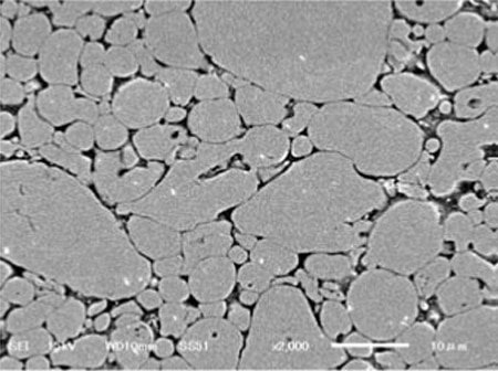
Figure 1: This SEM image shows the absence (black areas) of an organic binder in Taiyo Yuden’s new metal magnetic compacted power material.
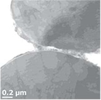
Figure 2: A TEM image of the new material illustrates the thin oxide layer that forms on the surface of the metal magnetic particles in Taiyo Yuden’s new material.
Since the composition of the oxide layer is compatible with the metal magnetic particles, it provides excellent insulation characteristics for the metal magnetic particle surface. Moreover, the oxide layer features high crystallinity – there are no defects in the oxide layer between adjacent metal magnetic particles and the crystals are connected continuously to one another. Given these qualities and the ability to control this layer to between 100 and 200 nm thick, the oxide layer makes it possible to secure the insulation and mechanical strength between metal magnetic particles. This characteristic allows the new material to offer excellent performance characteristics for choke coil applications.
To measure the benefits of this high-crystalline, thin oxide layer on material characteristics for choke coil applications, engineers at Taiyo Yuden tested the new material in three ways: bending strength, insulation and magnetic permeability. Details of the testing procedures and results are presented in Appendix B at the end of this article.
New MCOIL™ products
To address today’s increasingly challenging design requirements, Taiyo Yuden has developed a new family of products based on this new metal magnetic powder called the Metal Power Inductors MCOIL line. The new devices feature a metal magnetic core with permeability about 2x better than traditional composite-type power inductors. It also features a Hi-µ shielded resin and wound wire on the core. The products will be available in three series. The MC type is extremely-low-profile devices capable of supporting current levels in the 2 A to 3 A range. The MA type supports slightly higher current levels up to about 5 A in a slightly larger footprint. Finally, the larger MD type devices support even higher current levels in the 6 A to 7 A range.
Performance advantages over ferrite-based devices
The graphs shown in Figure 3 illustrate the significant performance advantage of a new MCOIL MDMK4040-type device over a comparable ferrite-based NRS4012-type device. With the ferrite device, inductance drops dramatically once DC Bias exceeds 2 A. Leveraging the advantages of its new metal magnetic powder, the MCOIL device exhibits far more stable performance. As the first graph indicates, inductance decreases slowly as DC Bias increases from 2 A to 8 A. Clearly the MCOIL device does not saturate as fast as the ferrite-based devices, allowing it to support higher levels of current.
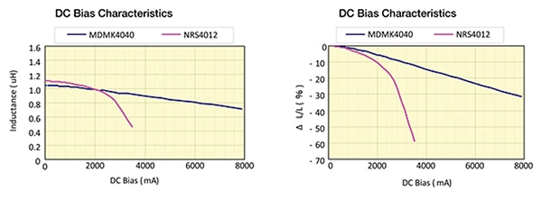
Figure 3: The left graph compares the inductance of the MCOIL device compared with its ferrite-based equivalent at various levels of DC Bias. The right graph depicts the saturation effects as DC Bias is increased.
Multiple advantages
By combining the advantages of the metal magnetic material with advances in process technology, the new MCOIL products also offer substantial space savings over earlier ferrite-type products. For example, Taiyo Yuden’s ferrite-based NRS6014T1R2MMGG devices come in a 6 x 6 x 1.4 mm footprint. Offering equivalent performance, the MCOIL MDMK4040T1R2 device occupies 56% less space in a compact 4 x 4 x 1.2 mm package. Similarly, the MCOIL 2.5 x 2.0 x 1.2 mm MAMK2520T1R0 offers comparable performance to the 4.0 x 4.0 x 1.2 mm ferrite-based NRS4012T1R0NDGG in a 69% smaller footprint.
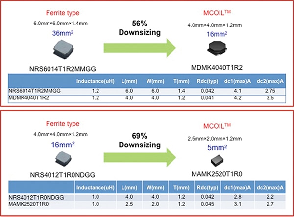
Figure 4: Size reduction with equivalent electrical performance of MCOIL devices compared to ferrite-based equivalents.
Recently Taiyo Yuden announced production of even lower profile devices in its Metal Power Inductors MCOIL line. Targeted at smartphones, tablets and SSDs, the MDKK1616 and MDKK2020 devices are 1.64 x 1.64 mm and 2.0 x 2.0 mm square respectively with a maximum height of only 1 mm. Taiyo Yuden is also offering a 2.0 x 1.64 x 1.0 mm device.
The new MCOIL line also offers significant advantages in terms of RFI shielding. As the graphic below illustrates, the emissions from a metal-based MCOIL MAMK2520T device are far lower than a comparable ferrite-based alternative. This characteristic improves performance and simplifies board design in multiple ways including reduced noise on other surrounding circuits, minimizing efficiency loss when the shield case or other components are near the power coil, and minimizing crosstalk with other power coils.
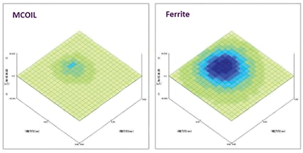
Figure 5: RF emissions from an MCOIL device compared with equivalent ferrite-based device.
Extensive testing by engineers at Taiyo Yuden also highlights the inherent advantages of the MCOIL inductors compared to competitors’ wire-wound ferrite or metal-type alternatives. As Figure 6a indicates, MCOIL products offer a far more gradual decline in DC bias characteristics than competitive wire-wound ferrite-type products that typically feature a rapid drop off in performance. This capability is central to MCOIL devices’ ability to support higher current levels in smaller footprints. Moreover, the new inductors demonstrate stable DC bias characteristics against temperature (Figure 6b). The MCOIL line also exhibits significantly lower AC resistance and higher efficiency than competitive wire-wound ferrite products (Figure 6c).
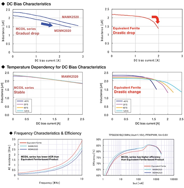
Figure 6: Performance comparison of MCOIL vs. ferrite-based wire-wound equivalents shows dramatic improvements in DC bias (6a), temperature (6b), AC resistance and efficiency (6c).
Performance advantages over composite metal devices
As discussed earlier, designers are looking to find alternatives to ferrite-based inductors. As a result, there are now alternatives that use compacted metal powder made of high-saturation magnetic flux iron-based metal magnetic particles and an organic binder. As already shown, the MCOIL products clearly out-perform ferrite-based equivalents in physical size, DC characteristics, RF, AC resistance and efficiency. However, what about comparisons with the newer metal powder devices? Figure 7 below showcases MCOIL’s competitive advantages over metal-type inductors. Here MCOIL offers significantly better AC resistance and Q factor. It also offers better power supply efficiency. Additional testing also confirms the robust nature and performance of the MCOIL material. (See Appendix A for a detailed discussion of these tests.)
Frequency characteristics
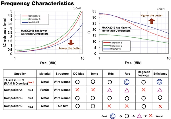
Figure 7: Comparison of MCOIL performance with competitive metal composite inductors.
Conclusion
Higher performance mobile devices offer a promising market for power inductor manufacturers. However, that opportunity will only become a reality if inductor suppliers can deliver the performance mobile device designers need in the low-profile footprint they require. By eliminating the use of an organic binder and improving permeability and insulation capabilities, the metallic magnetic material used in the MCOIL line has allowed engineers at Taiyo Yuden to reduce coil size without compromising performance. Together these advances have opened the door to a new generation of metal power inductors for mobile applications.
Appendix A. MCOIL Inductor Product Specifications

Appendix B. Performance Testing of MCOIL Material
To measure the benefits of this high-crystalline, thin oxide layer on material characteristics for choke coil applications, engineers at Taiyo Yuden tested the new material in three ways: bending strength, insulation and magnetic permeability. As a benchmark, the company used a material equivalent to a traditional metal composite material. This composite material was constructed by mixing an organic binder with an atomized powder composed of Ferrochrome Silicon (FeSiCr). Next, the engineers performed a uniaxial press forming process followed by thermosetting of the binder.
The first test measured three-point bending strength. Engineers began by creating a 50 mm long, 10 mm wide, and 4 mm thick plate-shaped sample. Next, by applying a load of 0.5 mm/minute at the load point, the development team calculated the bending strength of both the composite material and the metal magnetic powder material based on the maximum load measured at the time when each sample was destroyed.
The test results showed that the three-point bending strength of the composite material was approximately 8.0 kgf/mm² while the value for the metal magnetic powder material was 15.0 kgf/mm². The bending strength of the new material was significantly higher than the composite material. Engineers concluded that the formation of the dense oxide layer on the metal magnetic particle surface and its ability to connect metal magnetic particles continuously to one another resulted in a significantly higher bending strength.
In the next test, engineers measured the insulation capabilities of each material by forming electrodes on the top and bottom of a 50 mm diameter by 2 mm thick disc-shaped sample. Insulation properties were then measured using a HIOKO DSM-8104 Digital Super Megohmmeter Ultra-Insulation/Micro Ammeter. This test showed that the insulation resistance of both the composite material and the Metal Magnetic Powder material was approximately 106 Ω/cm.
Figure A offers a little more insight into the different insulation properties of the two materials. The graph shows that the breaking voltage of the metal magnetic powder material, at 3.6 x 10⁴ V/m, was higher than the breaking voltage for the composite material at 2.5 x 10⁴ V/m. This distinction indicates that the high-crystalline oxide layer formed on the metal magnetic particle surface offers high insulation properties. The ability of the metal magnetic powder material to achieve high resistance while maintaining its strength through its composition has significant implications from a manufacturing productivity perspective. It means that manufacturers can handle the new metal magnetic powder material using the same proven methodologies used for high-insulation ceramic materials such as nickel and zinc (NiZn) ferrites.
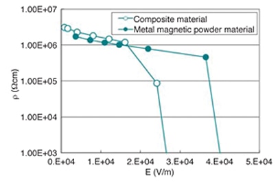
Figure A: Comparison of voltage breakdown characteristics of composite material vs. Taiyo Yuden metal magnetic powder.
The third test measured the magnetic permeability of each material. Figure B shows the results of the test. The graph indicates that magnetic permeability of the composite material is about 25 while the magnetic permeability of the metal magnetic powder material is about 45. Despite this difference, both materials exhibit almost identical frequency characteristics. Given these facts, it appears that the oxide layer in the metal magnetic powder material offers sufficient insulation characteristics and reduces eddy-current loss. Engineers deduced from these conclusions that the metal magnetic powder material offers higher magnetic permeability because the oxide layer is very thin and there are mutual magnetic reactions between the particles.
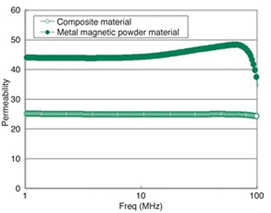
Figure B: A comparison of the magnetic permeability of the composite material vs. Taiyo Yuden magnetic powder.
Overall, this new material developed by engineers at Taiyo Yuden offers two basic advantages. First, it allows DC resistance to be controlled to a very low level by utilizing the material’s high magnetic permeability without compromising its excellent DC superimposition characteristics. This makes it possible to design inductors with lower DC resistance and capable of passing high levels of current. Second, since the material has a high insulation characteristic, inductor manufacturers can use the same highly developed manufacturing process used for ferrite materials. This characteristic offers significant productivity benefits.

免责声明:各个作者和/或论坛参与者在本网站发表的观点、看法和意见不代表 DigiKey 的观点、看法和意见,也不代表 DigiKey 官方政策。


