Managing the Energy and Lifetimes of Thin-Film Batteries
投稿人:Convergence Promotions LLC
2012-11-21
The development of wireless sensing technology has made possible tasks that would have been unthinkable in years past. Sensors can be installed where it is impractical or impossible to run a communication wire; their ability to communicate wirelessly, as long as they are within range of a hub, means that it is possible to gather data in places or situations that were previously inaccessible.
The inability to run a communication wire to the sensor also means no power line as well. Sensors need power both to sense and to communicate, so that has typically meant using a primary battery. While you would presumably select a battery with as long a life as possible, the battery is still unlikely to outlast the life of the sensor, meaning that someone will have to go out and replace the battery at some point – which can be expensive.
The alternative is to use energy harvesting so that the node becomes self-sufficient – a so-called “zero-power system.” However, energy harvesting sources are not constant, so storage is still required to accumulate energy when generation is productive and to use the stored excess when production slows. Such an application makes specific demands on the storage: it must be rechargeable using the small currents that energy harvesting generates; it must be able to handle many recharging cycles; it must be free of the risk of damage during charging; and it must be effective in a mode where the battery operates near capacity, cycling up and down by a few percent.
Thin-film technology
Thin-film batteries excel in this environment. They store enough energy to drive typical wireless nodes and their communication circuits while being specifically suited to charging by energy harvesting as well as by conventional methods. Two prominent vendors of thin-film batteries are Cymbet, with their EnerChip™ series, and Infinite Power Solutions (IPS), with their THINERGY® MEC series. Both companies use solid-state technology adapted from Oak Ridge Labs, although they have each taken that seed technology in somewhat different directions. The batteries are available in capacities from 1 µAh to 2.2 mAh.
The battery technology is based on lithium, but it is different from the better-known lithium batteries that have powered laptop computers and other gadgets for years. Those use a liquid electrolyte, and, if they’re not managed properly – that is, if the temperature, currents, or voltage are too high, metallic lithium can plate out between the cathode and anode, creating “dendrites” and the risk – and occasional occurrence – of a short that, combined with a flammable electrolyte, can damage the battery permanently or even present a risk of user injury.
By contrast, thin-film batteries are constructed with a solid-state electrolyte – a material referred to as LiPON (lithium phosphorus oxynitride). This material has the benefit of allowing the ready flow of lithium ions for high currents while being relatively impermeable to electrons, minimizing leakage. As a result, the batteries feature self-discharge rates on the order of a few percent per year.
The LiPON electrolyte is sandwiched between a LiCoO2 cathode and a metallic lithium anode (see Figure 1). Cymbet uses a silicon substrate housed in surface-mount packaging or shipped as bare dice that are 100 times smaller than a coin cell battery; IPS manufactures their units on a metal foil substrate, yielding a flexible battery. For either device, the entire unit is built with only inorganic materials.

Figure 1: A cross-section of a solid-state thin-film energy cell (Courtesy of Infinite Power Solutions).
Extending the battery lifetime
The number of charging cycles for a thin-film battery can range from the thousands to the tens of thousands to the hundreds of thousands of cycles, depending on the battery, environmental conditions, and how far the battery is discharged on average. In contrast to the memory effect of past generations of storage, the lifetime of a thin-film battery is improved by shallower discharges.
Limiting discharge to 10 percent depth-of-discharge (DoD) (meaning that 90 percent of the capacity of the battery remains) can boost battery life by 10 times over 80 percent DoD usage. This high number of recharge cycles effectively means that the battery is likely to outlive the actual sensor that it’s powering, meaning that no one needs to go out and replace the battery until the entire sensor unit itself needs replacing.
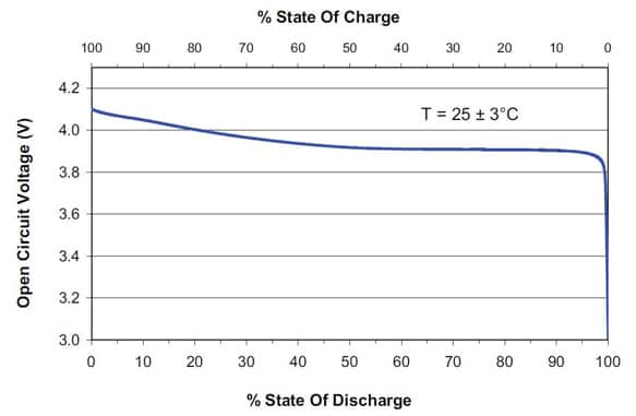
On the other hand, deep discharging, if taken too far, can damage the battery. The voltage should, in general, never go below a minimum voltage (Cymbet recommends 3 V; IPS nominally recommends 3 V as well, but can tolerate 2.1 V for higher-current applications). The reason for this is a rapid drop-off in voltage as discharge progresses (see Figure 2). At some point, the battery chemistry changes, and the battery will be permanently damaged – it may even look like a short.
The rapid drop-off makes it safer to stop at a higher voltage level, especially with low current draw, unless discharge is managed by circuitry fast enough to react when the drop starts. It is for this reason that, with IPS, 3 V is a safer stopping point than 2.1 V.

Figure 2: Voltage drops off rapidly as the charge approaches the end of its useful life (Courtesy of Infinite Power Solutions).
Recharging
Lithium batteries traditionally have a two-step charging procedure. There is a lag in the movement of ions as the battery charges; it is like tugging hard on an elastic string with a ball attached to the other end. When you tug, your hand will get to its final position before the ball even moves; the ball then reacts to the elastic and moves while you hold your hand in the final position, giving a two-step process: constant hand movement followed by constant hand position.
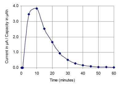
Likewise, when charging lithium batteries, one typically starts with a constant-current (CC) phase, using current-limiting circuitry. During this time, the voltage will increase to about 4.1 V. At that point, you switch to a constant-voltage (CV) phase, during which the current gradually slows as charging completes.
While this CC/CV approach can be used with thin-film batteries, they also allow a CV-only charge, since the internal resistance of the battery provides enough current limiting as long as the voltage isn’t too high. If future batteries feature lower resistance, then a CC/CV approach may become necessary; for now it’s optional. An example of the current characteristics while charging is shown in Figure 3.

Figure 3: The current drawn during charging using a constant voltage (Courtesy of Cymbet).
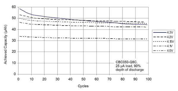
Charging the batteries with a higher voltage will deliver more charge to the battery, but it comes at the expense of battery life. With higher charging voltages, the battery may experience faster “cycle fade,” meaning that, over time, each charging cycle will store less power. Even the difference between a 4.0 V charge and a 4.3 V charge can be substantial, as can be seen in Figure 4.

Figure 4: Higher charging voltages store more charge, but cause the cell to exhibit greater "cycle fade" (Courtesy of Cymbet).
For both Cymbet and IPS, the recommended charging voltage is 4.1 V. IPS has a 4.15 V maximum; Cymbet has a 4.3 V maximum.
Traditional lithium ion battery technology requires careful attention to prevent over-charging. Thin-film batteries, by contrast, are much more forgiving. Once charged, they can be maintained in a trickle-charging mode, which is ideal for remote sensors that may draw only a little power during a wake-up cycle; that small draw can be quickly topped off by energy harvesters providing a trickle charge.
Managing charge and discharge
ASICs are available for managing the energy state of the batteries for both charge and discharge. These devices are generically referred to as Power Management ICs (PMICs). Texas Instruments, Linear Technology, and Maxim make PMICs that can be used with the Cymbet and IPS cells and Cymbet makes its own PMICs that it calls “energy processors.”
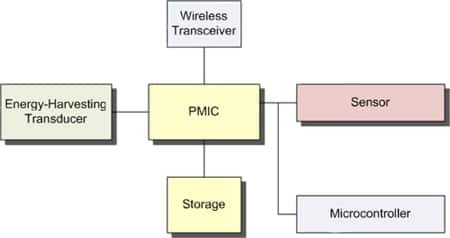
The PMICs have a variety of capabilities, and, together with the battery and energy harvesting transducers, form the power subsystem of a sensor node. Some of the PMICs can interface with a microcontroller for management. In the best case, these components can be combined with a communications node to form a zero-power system that can supply its own power needs (see Figure 5).

Figure 5: A "zero-power" wireless sensor node with its own energy source, storage, sensor, controller, and transceiver.
Some PMICs can do more than just make sure that the battery is charged or discharged properly. They also extract the most power possible from the energy harvester through Maximum Peak Power Tracking (MPPT). In order to optimize the power extracted from the harvester, the energy management chip must match the impedance of the harvesting system. Different harvesting technologies have different impedances, most of which are constant; as soon as you match such a device, there’s no further need to adjust the impedance.
Solar cells, however, have impedance that changes over time. MPPT allows a PMIC to track the input impedance as it changes, matching it for optimal efficiency.
Because of the different voltage ranges that different transducers provide, there are typically settings (either pull-up/down or resistor values) that configure the PMIC for the appropriate range. Electromagnetic and piezo-electric transducers generate alternating current, which must be rectified prior to delivering the current to the PMIC.
A totally self-powered node means that the PMIC itself must be powered from the harvested energy. That necessitates a so-called “cold boot” process whereby energy is first supplied to power the PMIC; once up and running, powering up continues as the harvested power is sampled to set the impedance.
An important energy harvesting consideration is the fact that energy management itself consumes power. More intelligent management tends to consume more power. This increases the “break-even” point below which the harvested energy cannot keep up with the needs of the management circuits. Thus, there is a trade-off between the optimal energy that can be captured and the point below which the system is in net energy deficit.
Available PMICs
The following illustrate a selection of PMICs, focusing on those that are known to work well with the Cymbet and IPS thin-film batteries.
Cymbet
Cymbet provides its own energy processor, both stand-alone and integrated with a battery.
The CBC915 is a PMIC that provides over- and under-voltage protection for a battery, MPPT for a harvester, and communication with a microcontroller for monitoring status and controlling the energy processor. The chip is housed in a 38-pin TSSOP package.
The EnerChip CC series combines a PMIC and an EnerChip battery in a single unit. The energy processor can be used to manage both the internal battery and up to an additional 10 EnerChip batteries connected in parallel. This device comes in packages ranging from a 4 mm x 5 mm DFN (dual flat no-leads) to a 9 mm x 9 mm DFN package.
Linear Technology
Linear provides the LTC4071 in an 8-pin DFN (3 mm x 2 mm) or MSOP (mini- or micro-small-outline package). It is intended for use with a number of lithium-ion batteries, including thin-film batteries from Cymbet and IPS. The device’s primary duties relate to switching out a battery when it reaches a programmed state of discharge to prevent under-voltages. It can also reduce the charging (or “float”) voltage if the temperature of the battery gets too high through the use of a negative temperature coefficient (NTC) thermistor. It is intended to be driven either by wall power or by energy harvesting subsystems.
Maxim
The MAX17710 is a charging and management chip designed with the IPS THINERGY cells in mind, although it should also work with other cells that are similar to the IPS cells. Its main functions are for charging, with over-voltage protection, and for managing discharge to avoid under-voltage operation. It is housed in a 3 mm x 3 mm ultra-thin DFN (UTDFN) package.
The MAX17710 provides both low input voltage boost and MPPT. Its low-dropout (LDO) regulator can be controlled by a microcontroller or other event detector.
Texas Instruments
The TI BQ25504 is intended for use managing a wide variety of batteries and storage capacitors. It provides input boost and MPPT, output regulation, and over- and under-voltage protection. It is available in a 3 mm x 3 mm QFN (quad flat no-lead) package.
Development boards
A number of development and evaluation kits are available for demonstrating the use of thin-film batteries in energy harvesting and other applications. The following are brief outlines of a sampling; more examples and discussion can be found in the article, “Development Kits Reduce Time to Design Energy Harvesting Applications.”
Cymbet EnerChip CC CBC3112 and CBC3150 Evaluation Kit (CBC-EVAL-05)
This evaluation board contains two EnerChip CC devices, a CBC3112 and a CBC3150, providing its own management and 12 µAh and 50 µAh batteries in parallel. The kit can be used for evaluating the battery technology, the management function of either chip, or the ability of an EnerChip CC device to manage itself and another battery. The board is mounted atop a 24-pin DIP pin format that can be plugged into a 24-pin DIP socket on an application board.
Cymbet EnerChip EP Universal Energy Harvester Evaluation Kit (CBC-EVAL-09)
This development kit is intended for use in building energy harvesting applications. It features a CBC915 PMIC and a CBC51100 module with 100 µAh of storage. While it can be used with a variety of transducers, it ships with a solar cell for initial evaluation.
Cymbet EnerChip CC Energy Harvester Evaluation Kit (CBC-EVAL-10)
This energy harvesting development board features the CBC51100, with a CBC3150 processor/battery and a CBC050 battery for 100 µAh of storage. It includes a photovoltaic panel for generating power.
IPS MEC/Energy Harvesting Evaluation Kit (IPS-EVAL-EH-01)
This kit is intended for development of energy harvesting applications. It features an IPS MEC201-7S 700 µAh cell with a Maxim MAX17710 PMIC. It comes with a solar panel, but users can connect their own energy harvesters as well.
Summary
Wireless sensor networks are bringing smart technologies to applications that were never possible before. Energy harvesting is critical to those applications, requiring efficient energy capture and storage in small, rechargeable batteries with long lifetimes. Thin-film batteries from companies like Cymbet and IPS, managed by PMICs from companies such as Cymbet, Linear Technology, Maxim and Texas Instruments, have become essential components in the design of these zero-power sensor nodes.

免责声明:各个作者和/或论坛参与者在本网站发表的观点、看法和意见不代表 DigiKey 的观点、看法和意见,也不代表 DigiKey 官方政策。


 中国
中国